Deploy Secure Mesh Site v2 in AWS (ClickOps)
Objective
This guide provides instructions on how to create a Customer Edge (CE) Site using F5® Distributed Cloud Console and Amazon Web Services (AWS) Management Console and deploy to an AWS virtual private cloud (VPC).
Important: This guide does not provide instructions on how to deploy an F5® App Stack Site.
Planning
Read the following documents before deploying a Secure Mesh Site in any provider environment:
- Understanding F5 Distributed Cloud - Customer Edge (CE)
- CE Datasheet
- CE Supported Platforms Guide
- Customer Edge Site Sizing Reference
- CE Performance Guide: Contact your account representative on CE performance-related information.
- Proxy for CE Registration and Upgrades Reference
- Secure Mesh Sites v2 Frequently Asked Questions
- Customer Edge Registration and Upgrade Reference
- F5 Customer Edge IP Address and Domain Reference for Firewall or Proxy Settings
General Prerequisites
The following general prerequisites apply:
-
A Distributed Cloud Services Account. If you do not have an account, see Getting Started with Console.
-
An account with AWS with an IAM user with the IAM permissions mentioned in the AWS VPC Policies and Permissions Reference guide.
-
Resources required per node: Minimum 8 vCPUs, 32 GB RAM, and 80 GB disk storage. For a full listing of the resources required, see the Customer Edge Site Sizing Reference guide. All the nodes in a given CE Site should have the same resources regarding the compute, memory, and disk storage. When deploying in cloud environments, these nodes should use the same instance flavor.
-
Allow traffic between the Distributed Cloud public IP addresses and your network and allowlist-related domain names. See F5 Customer Edge IP Address and Domain Reference for Firewall or Proxy Settings guide for the list of IP addresses and domain names. At a minimum, you must allow egress traffic for Site registration and IPsec tunnel creation.
-
F5 assumes that the VPC exists with a minimum of a single subnet where the CE Site node is deployed. For three-node clusters, F5 recommends that you have three different subnets in three different Availability Zones (AZs).
-
The new Secure Mesh Site workflow enables you to have up to eight interfaces. However, these interfaces should be in different subnets. Therefore, make sure you have the required subnets available before creating the CE Site nodes.
Important: After you deploy the CE Site, the IP address for the SLO interface cannot be changed. Also, the MAC address cannot be changed.
Configuration Overview
To create a Secure Mesh Site with AWS, here are the high-level steps:
- Site object configuration: Create and configure a Secure Mesh Site object using F5 Distributed Cloud Console.
- Node deployment prerequisites: Create objects that are associated with the CE nodes, including security groups, SSH key pairs, and more.
- Node management: Use one of the launch methods to create the CE nodes (EC2 instances), and then configure the settings. Each CE node is a virtual machine (VM).
High Availability Option for Redundancy
There are two methods to enable redundancy using the High Availability (HA) option: (1) using the default multi-node (three-CE cluster) or (2) using a cluster type of two or more single nodes (also called network-based HA model). For more information, see the reference article.
For single-node HA configurations, F5 recommends that you use an AWS Network Load Balancer (NLB) with TCP protocol (and enabled with the cross-zone load balancing attribute) to manage ingress traffic across the CE nodes only if you plan to publish applications on the CE itself (rather than on an RE). In this configuration, the NLB acts as the single entry point (using the private or Public VIP), forwarding traffic to the secondary IP addresses on the active CE nodes.
Configuration in Distributed Cloud Console
Create Site Object
Create the Site object that you associate with your nodes.
-
Create a Secure Mesh Site object in Distributed Cloud Console. Refer to the Create Secure Mesh Site guide.
-
Set the Provider Name option to AWS.
-
For High Availability, choose an option. If Disabled, the CE Site operates as a single node. If Enabled, the multi-node CE Site mode (default HA model) is activated, which requires a minimum of three nodes (though more can be deployed). Refer to the High Availability Option section above to explore the available HA options in detail. When a multi-node CE Site is configured, all nodes must be provisioned at the same time. The provisioning process will not proceed until registration requests from all nodes are received.
Important: The High Availability mode cannot be changed after the CE Site object is created.
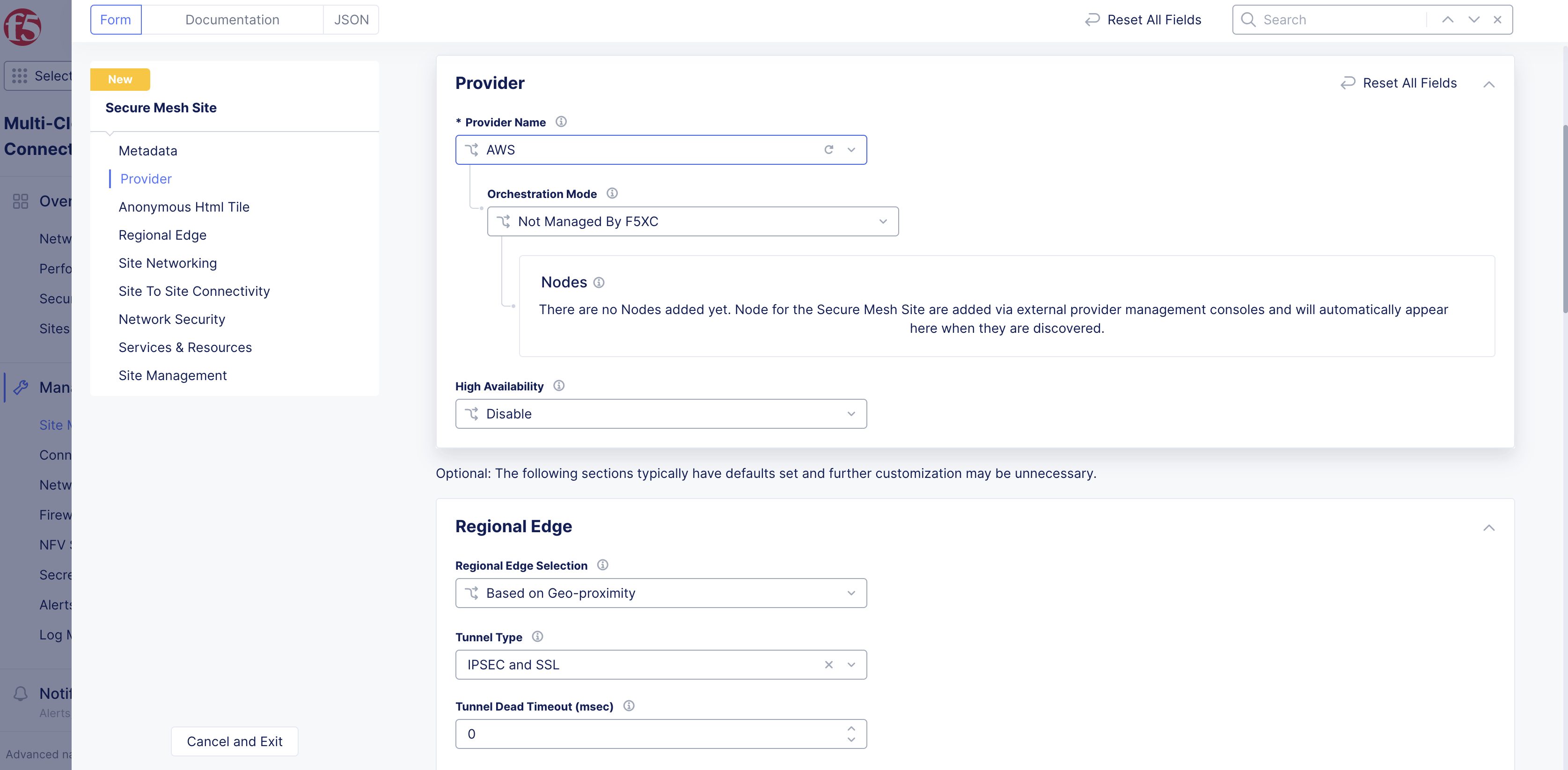
Figure: Provider Type
-
Leave the other options with their default values. These options have intelligent default values and do not need further configuration. Refer to the Create Secure Mesh Site guide for more information on these options.
-
Click Add Secure Mesh Site.
Generate Node Token
A one-time node token is required to register a CE Site node to the Distributed Cloud Console. A new token must be generated for every new node in a CE Site. A token is valid for 24 hours. When deploying multi-node CE (High Availability mode enabled), the timing of token generation is critical. Treat the deployment as a sequential process rather than generating all tokens upfront. First, generate the first token, then deploy the first node and wait at least 2-3 minutes for the node to boot up and complete the registration request before generating the next token.
The token is included in the cloud-init information under the Content variable. Also included are two variables commented out: slo_ip and slo_gateway. These variables can be uncommented out if you do not want to use the DHCP (dynamic IP address) and need to set the SLO interface IP address and gateway IP address statically.
-
In Distributed Cloud Console, select the Multi-Cloud Network Connect workspace.
-
Navigate to Manage > Site Management > Secure Mesh Sites v2.
-
For your Site, click ... > Generate Node Token.
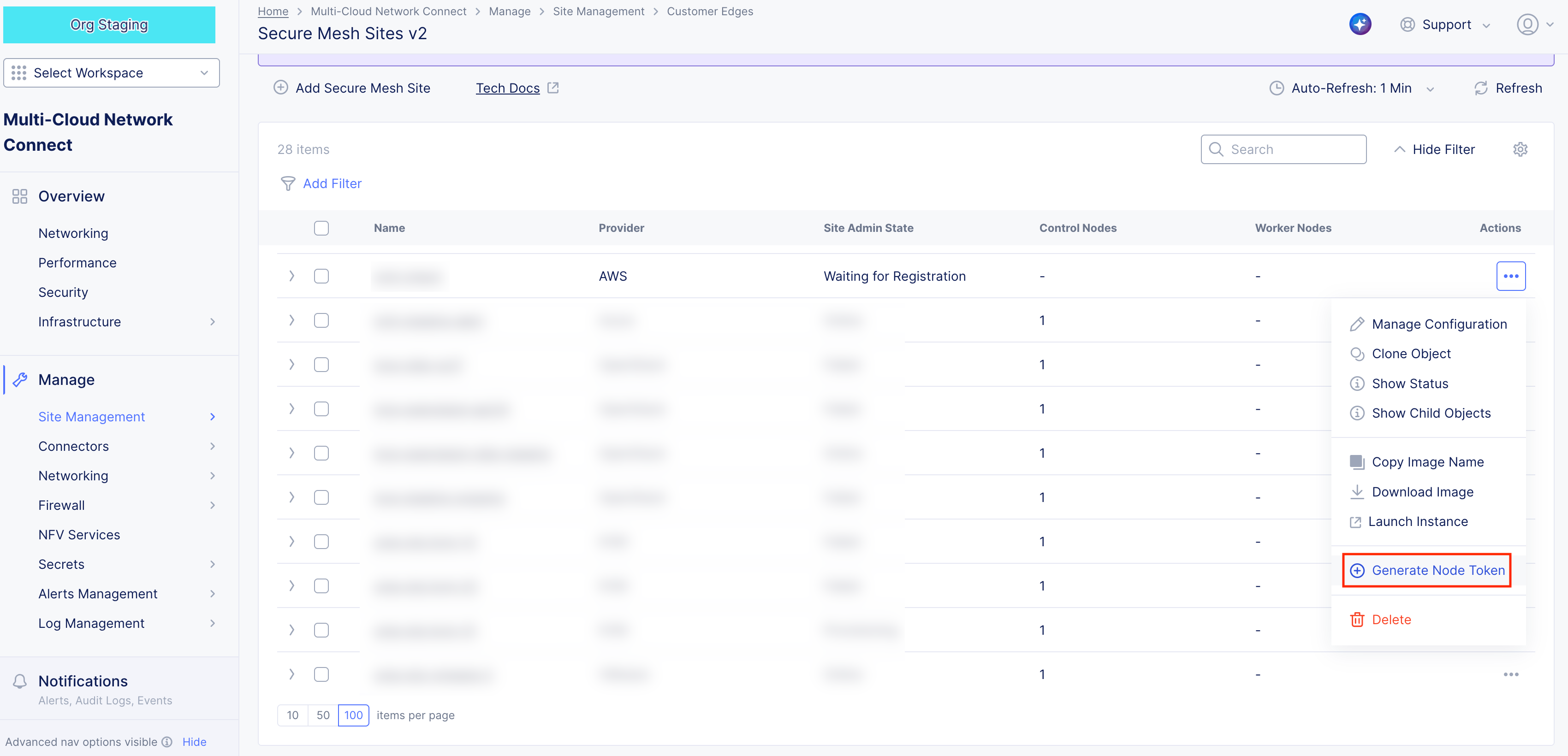
Figure: Generate Node Token
-
Click Copy cloud-init.
-
Save the value locally. This token is used later. The token value is hidden for security purposes.
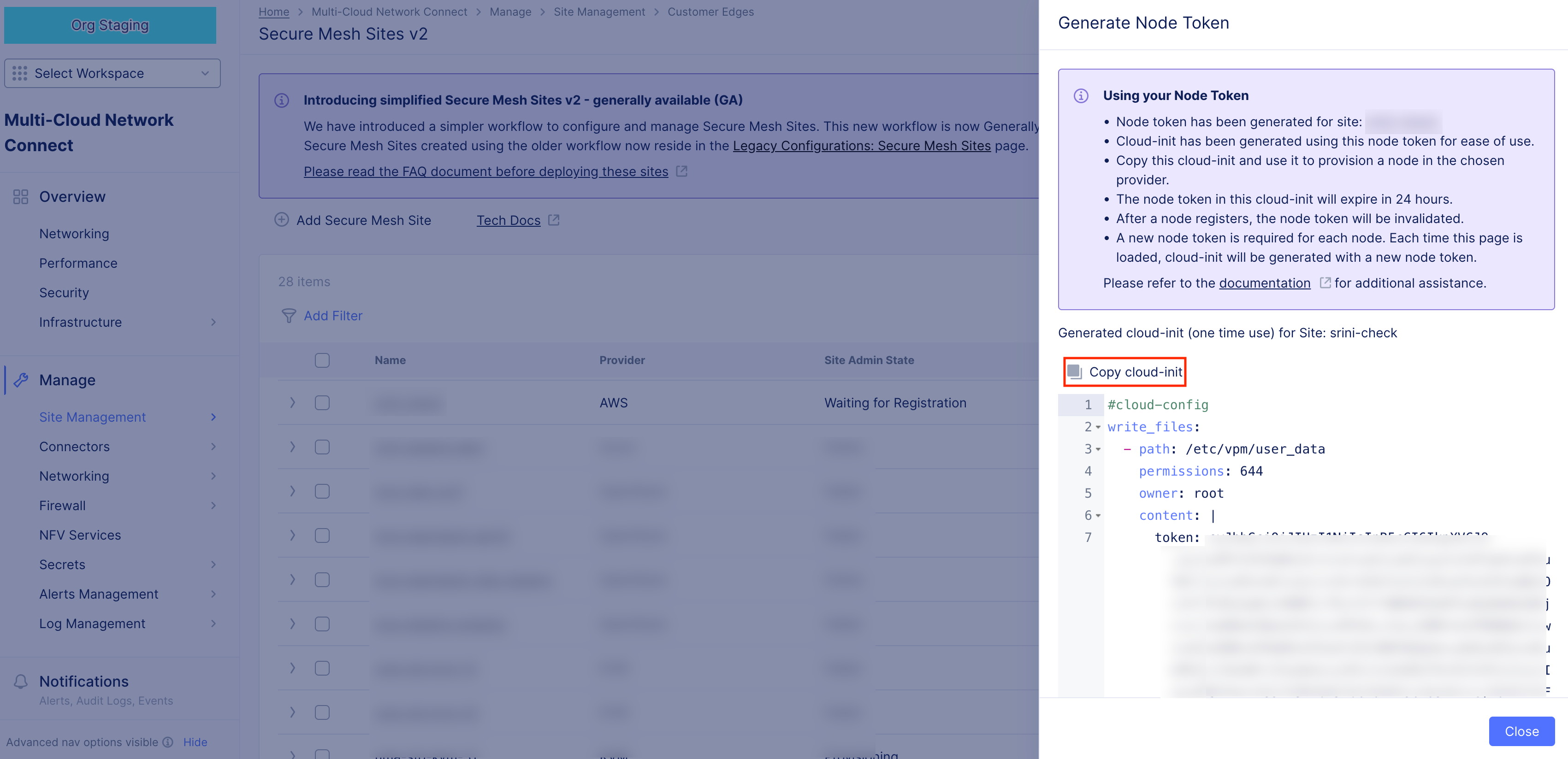
Figure: Node Token
-
Click Close.
-
Generate one token per node you deploy.
Configuration in AWS Management Console
Prepare VPC Resources
In this guide, a dual interface single-node CE Site is being deployed. Since the Site has two interfaces, two subnets are required. One for SLI and the other for SLO. Both subnets are in the same AWS Availability Zone (AZ). In this example, us-west-1c is the AZ where the SLI and SLO subnets are located.
You can create additional SLI interfaces to directly connect to more workload subnets if necessary. If your design requires these extra interfaces for traffic isolation or specific routing, F5 recommends that you provision them at this stage. While it is possible to add interfaces later, doing so post-deployment requires a reboot and service disruption. Each CE node supports up to eight network interfaces.
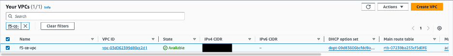
Figure: Existing VPC Details
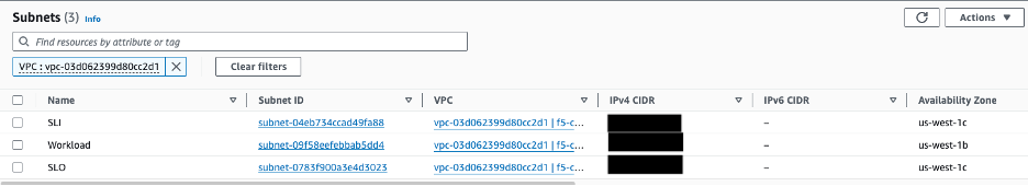
Figure: Existing Subnet Details
Create Security Group
Create the security group that is attached to your F5 CE Site EC2 instance (node). This security group is used for the Site Local Outside (SLO) interface. Security groups for any other Site Local Inside (SLI) interfaces can be created depending on your specific traffic requirements. At a minimum, create security groups for the SLI that allow traffic from each CE node to the pool members or from servers to the private VIP you may define on the SLI.
Step 1: Create security group.
-
In AWS Management Console, navigate to the EC2 service.
-
From the left panel, under Network & Security, click Security Groups.
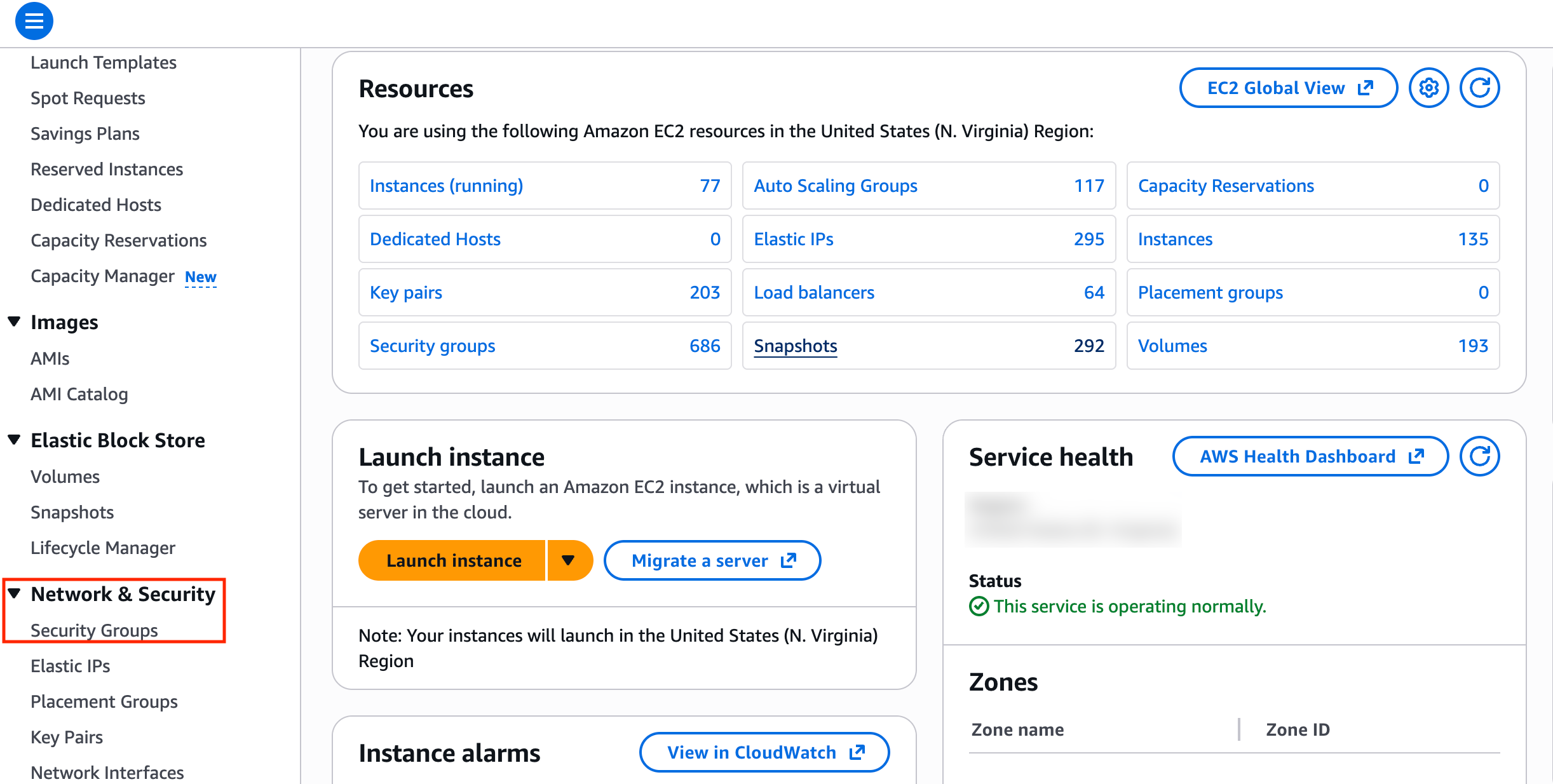
Figure: Security Groups
- Click Create security group.
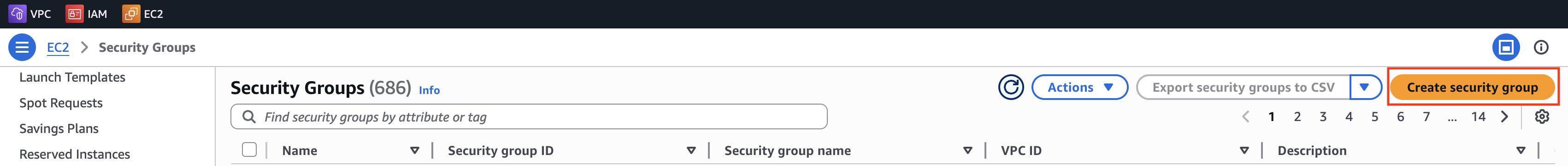
Figure: Security Groups
- Enter a name. For example, f5-ce-security-group.
Step 1.1: Create inbound rules.
For the inbound rules, refer to the F5 Customer Edge IP Address and Domain Reference for Firewall or Proxy Settings guide especially for multi-node CE Site requirements, Site Mesh Group, DC Cluster Group, eBGP peering, or External Connector.
When deploying a CE node, the security group configuration primarily focuses on ensuring outbound connectivity to the Regional Edge (RE) sites. For standard operations, the CE establishes an encrypted tunnel using outbound connections, which simplifies the security posture for many initial deployments. Note that to deploy a single CE node, you do not have to necessarily allow any traffic from the public Internet in an inbound direction unless you need to cover other use cases, such as public VIP on a CE or a Site Mesh Group (SMG).
In addition, you may want to cover the following:
-
Allow ICMP. This is used for troubleshooting purposes.
-
Occasionally, direct access may be helpful during node provisioning. In such cases, you can optionally allow SSH from a trusted IP address for administration, or allow TCP Port 65500 to access the local UI on the CE Site for troubleshooting. These rules are generally not required for standard operation.
-
Mandatory: For a multi-node CE deployment, ensure that all nodes within the Site can communicate with each other via the SLO and SLI interfaces. To achieve this, add an inbound rule that references the security group itself as the source. This permits traffic between all network interfaces (nodes) sharing that security group.
Important: If you configure an HTTP load balancer listening on HTTPs and advertised on the CE node, make sure you add a rule that allows HTTPs traffic from any source. You can also restrict the sources if there is a need.
Step 1.2: Create outbound rules.
You can choose to implement either an "allow all" egress policy or a more restrictive one. While a restricted policy offers tighter control, it typically only accounts for the connectivity required for the CE Site to function. It does not automatically accommodate broader connectivity needs within your environment, such as workload access to external domains and IP addresses, CE inter-node communication, Site Mesh Group or DC Cluster Group traffic, BGP peering, or other external connectivity scenarios. If you decide to use a restrictive policy, see the F5 Customer Edge IP Address and Domain Reference for Firewall or Proxy Settings guide for the list of IP addresses and domain names.
-
For outbound traffic, add an allow all policy.
-
After you finish, click Create security group.
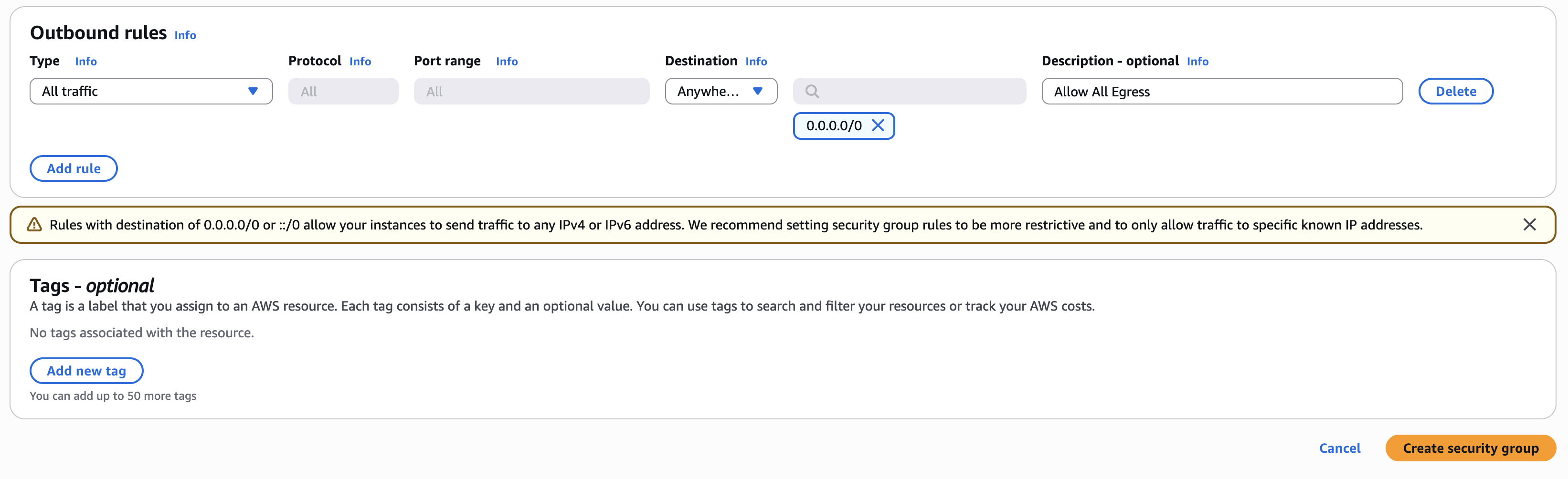
Figure: Outbound Rules
Step 2: Verify rules created.
Confirm rules created successfully. Use the Inbound rules and Outbound rules tabs to list the rules.
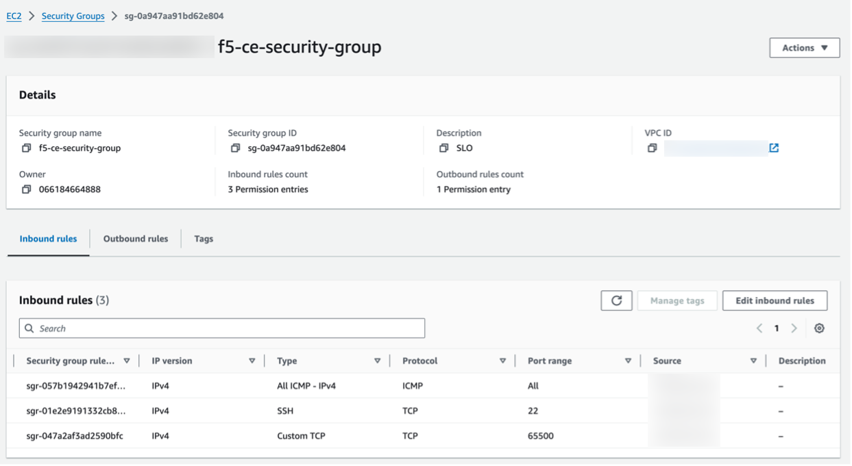
Figure: Verify Security Group Rules
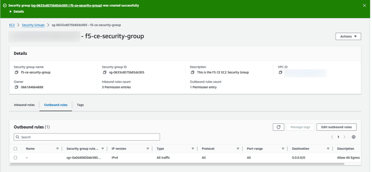
Figure: Verify Security Group Rules
Create SSH Key Pair - Optional
Create the key pair that is used for SSH log in to the EC2 instance (node) for troubleshooting purposes, if needed. You can create one pair and use it for all nodes in your CE Site.
Step 1: Create key pair.
-
In AWS Management Console, navigate to Network & Security > Key Pairs.
-
Click Create key pair.
-
Enter a name, and select the type of key pair.
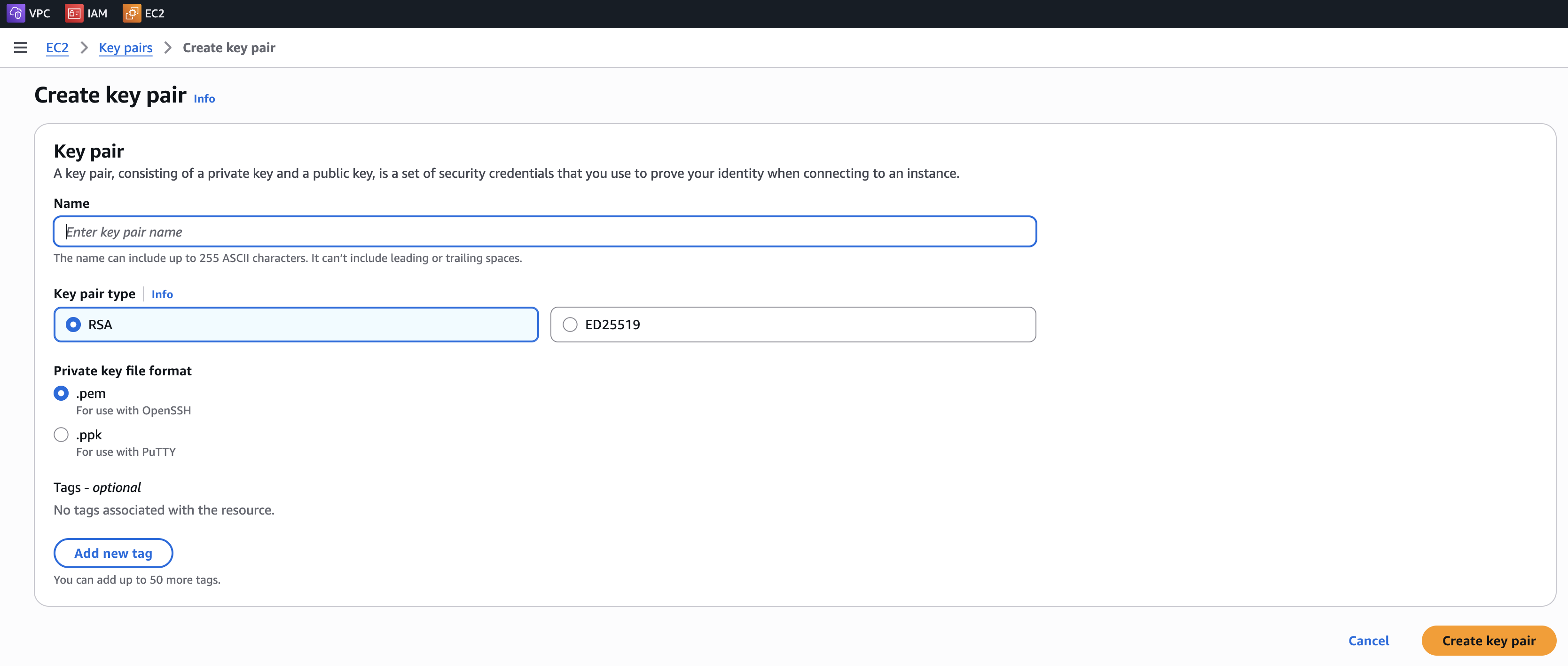
Figure: Create SSH Key
- Click Create key pair.
Step 2: Verify key pair.
Verify the SSH key pair was created.
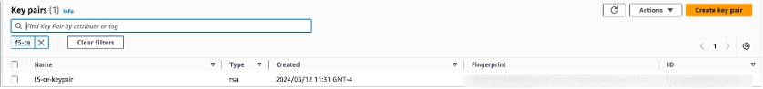
Figure: Verify SSH Key
Create AWS EC2 Instance
You can use one of three methods to initially launch your EC2 instance virtual machine (VM). You can (1) launch directly from AWS Marketplace, (2) launch using a public image (AMI) published by F5, or (3) launch using a downloaded image file. Afterwards, the configuration process is identical regardless of the launch method. Each VM is a node in your Site. For a multi-node CE Site, you must configure and launch three nodes.
Important: The name of the VM should not have "." in it. For example, the hostname can be node-0 or node0, but it cannot be node.f5.com since it is not supported. Your node VM name must adhere to DNS-1035 label requirements. This means the name must consist of lower case alphanumeric characters or “-“, start with an alphabetic character, and end with an alphanumeric character.
If configuring a multi-node Site, each node hostname must be unique.
Step 1: Launch node VM.
-
In Distributed Cloud Console, select the Multi-Cloud Network Connect workspace.
-
Navigate to Manage > Site Management > Secure Mesh Sites v2.
-
For your Site, click .... Select a launch method from the options available.
Option 1: Launch node VM directly from AWS Marketplace.
-
For your Site, click Launch Instance. This action opens the CE image listing in AWS Marketplace, in a new browser tab.
-
For the Launch Method drop-down menu, select Launch from EC2 Console.
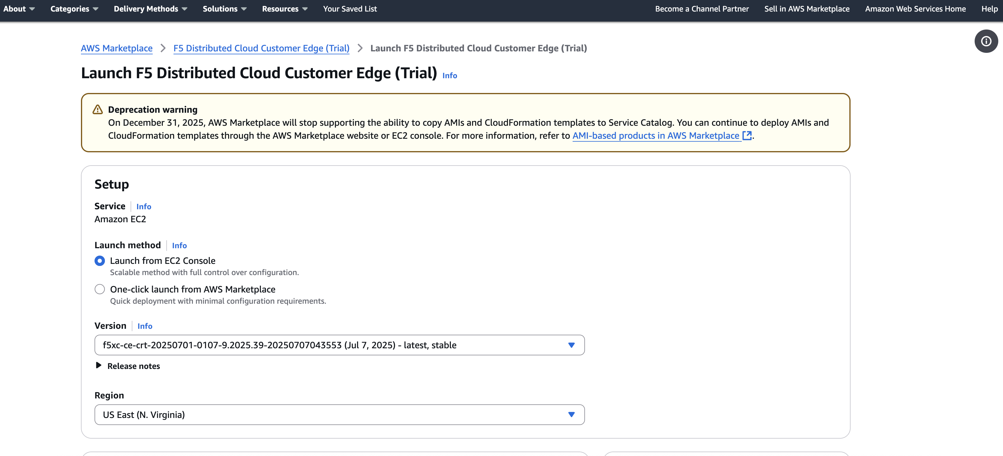
Figure: Launch Instance From EC2 Console
-
Confirm the Version is as desired. By default, the most recent software version is selected. Use the drop-down menu to select another version, if needed.
-
Confirm the Region is as desired.
-
Click Launch from EC2. A new browser tab opens.
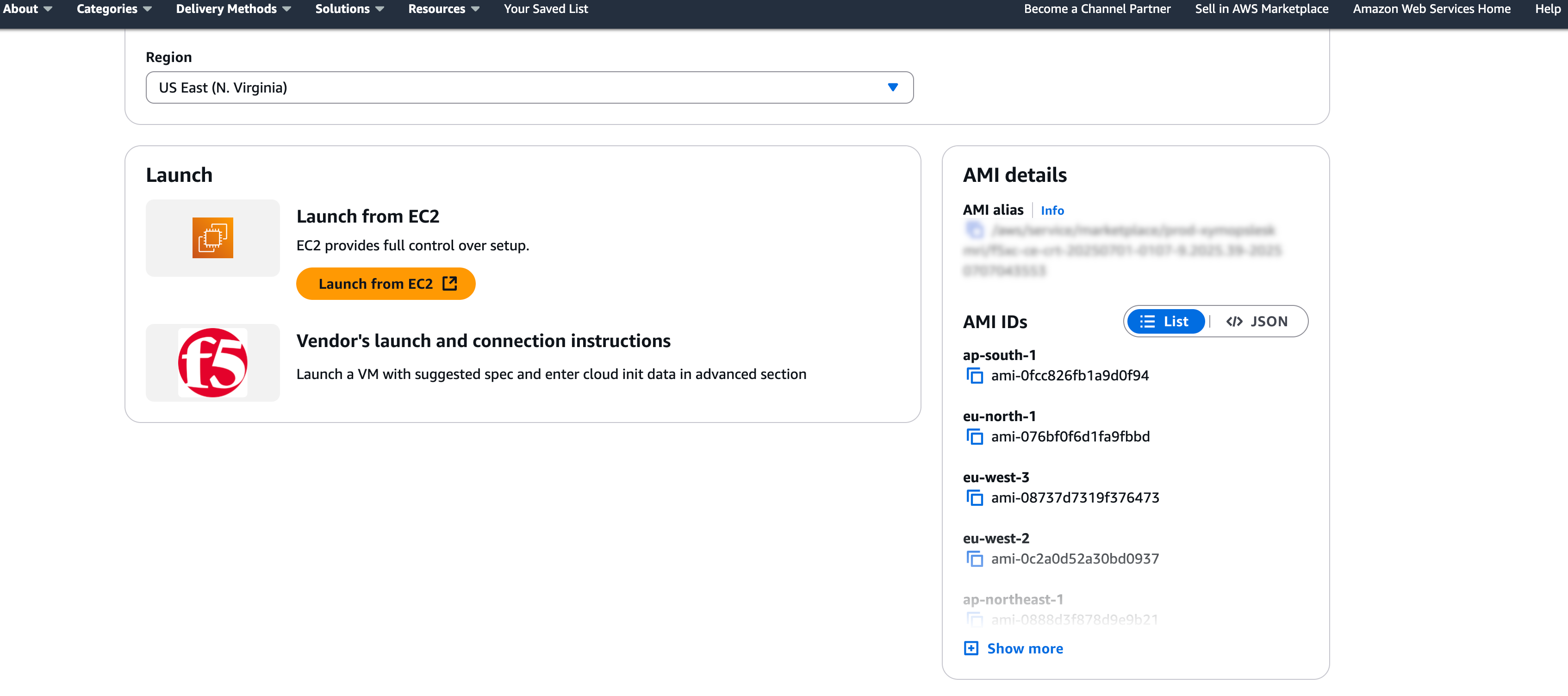
Figure: Launch Instance From EC2 Console
Option 2: Launch node VM with public AMI.
- For your Site, click ... > Copy Image Name. This action copies the AMI name within AWS. It is important to note that the AMI name for the CE Site node images are the same regardless of your chosen AWS region.
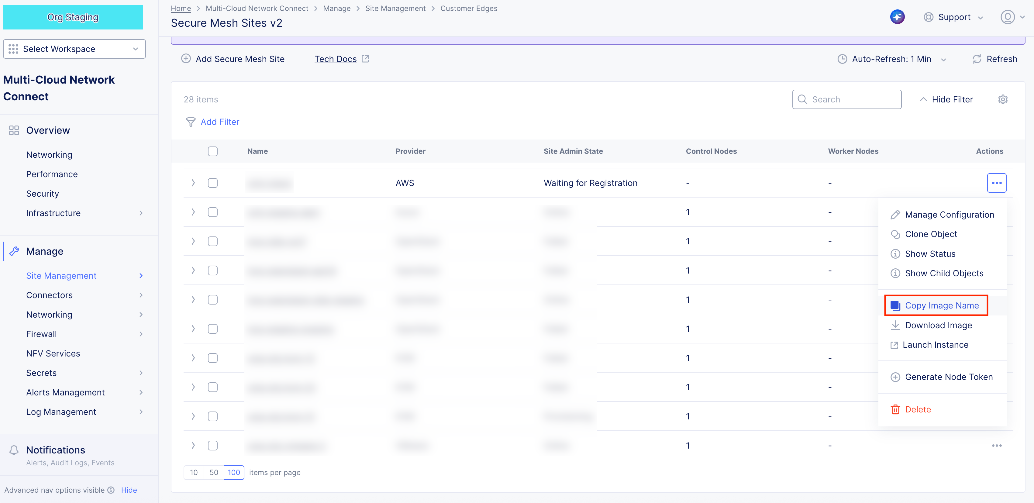
Figure: Copy Image Name
Note: The AMI name follows the naming convention of
f5xc-ce-crt-<version>. For example, f5xc-ce-crt-20250701-0195-9.2025.39-20251204172625. The copied image name is used to find the AMI in AWS Management Console.
-
In AWS Management Console, navigate to the EC2 service.
-
From the left panel, click Images > AMIs.
-
Select Public images.
-
In the search box, paste the AMI name. You should have one matching entry. The AMI name to look for is
f5xc-ce-crt-<version>, whereversionconsists of numbers only. If you have trouble finding the image, you can search manually with "f5xc-ce-crt" and locate the image with the latest date.
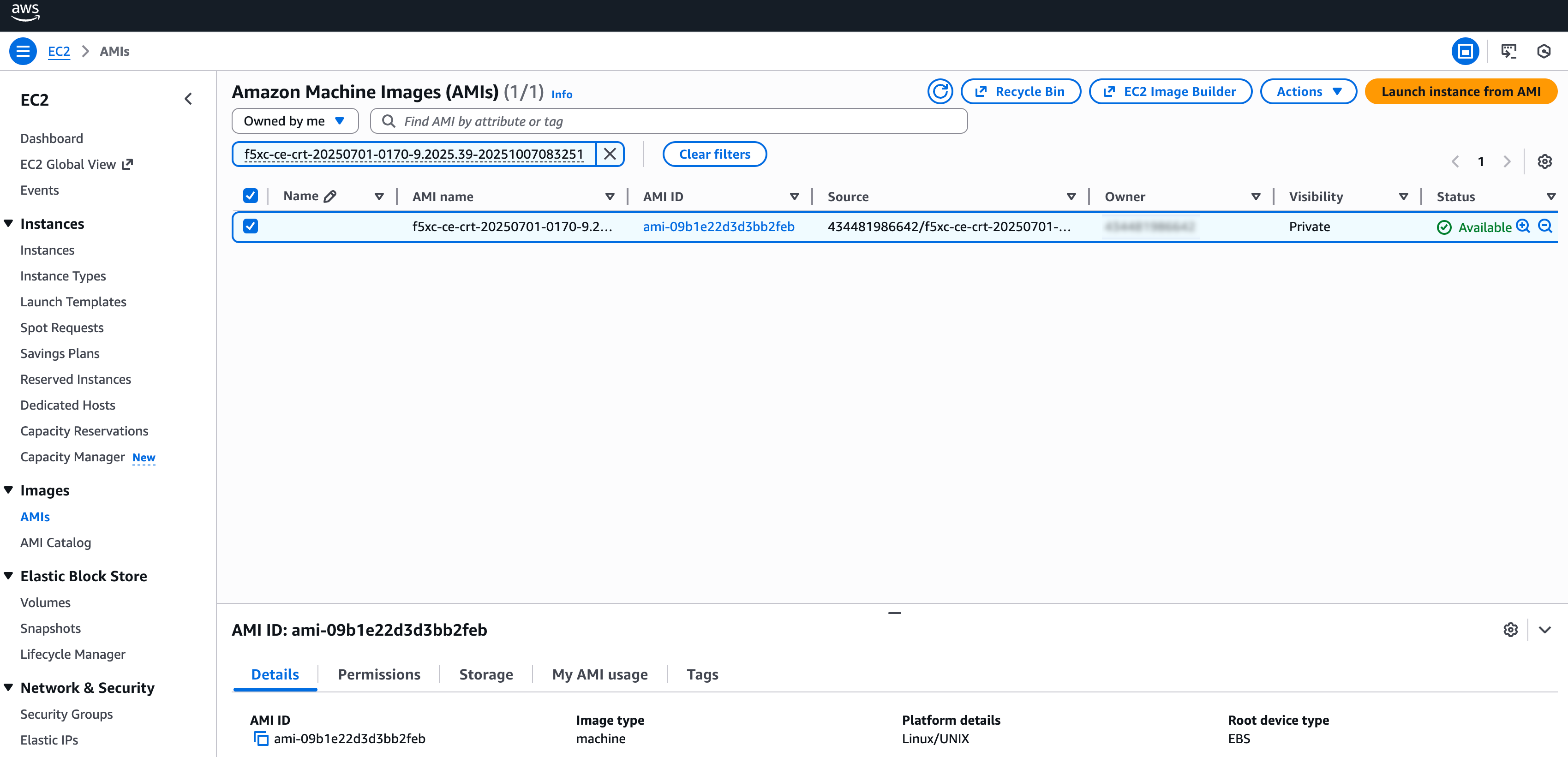
Figure: Find AMI Listing
-
Select the checkbox to select the image item.
-
Click Launch instance from AMI.
Note: For AMI troubleshooting issues, see Troubleshooting for AMI Listings.
Option 3: Launch node VM with downloaded image file.
If you do not have permissions for Community AMIs or AWS Marketplace or the AMI is not available in your region (local zone), use the download image option to create your own custom AMI.
- For your Site, click ... > Download Image. This action downloads the node image file onto your local machine.
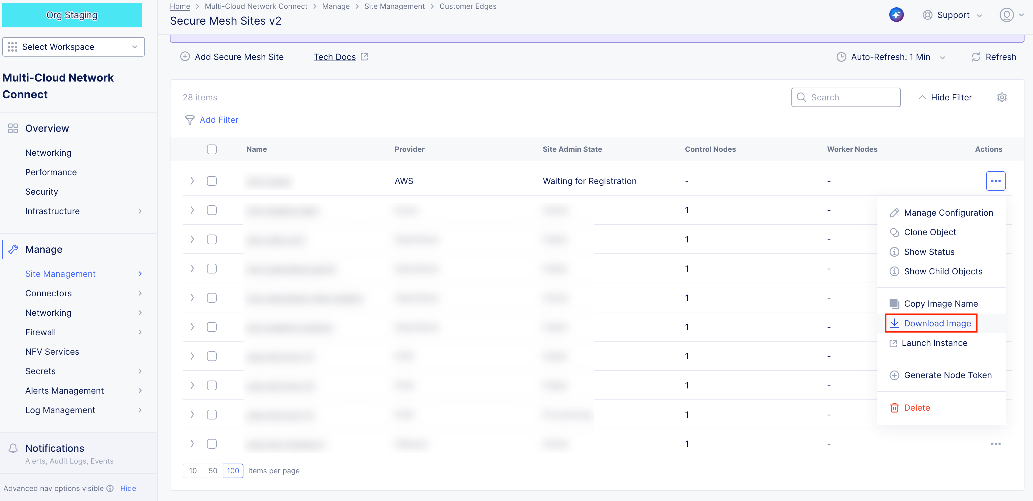
Figure: Download CE Node Image
-
In the side popout window, confirm the integrity of the downloaded file using the MD5 checksum value.
-
Afterwards, click Close.
-
Create an S3 bucket with a specific IAM service role (vmimport) in your target AWS region.
-
Upload the downloaded file to the S3 bucket.
-
Import the image via AWS CLI using the ec2 import-image command, referencing the S3 file and the vmimport role. For more information, see the official AWS documentation.
Step 2: Configure node VM.
- Under Name, enter a name for your VM. This is the node name.
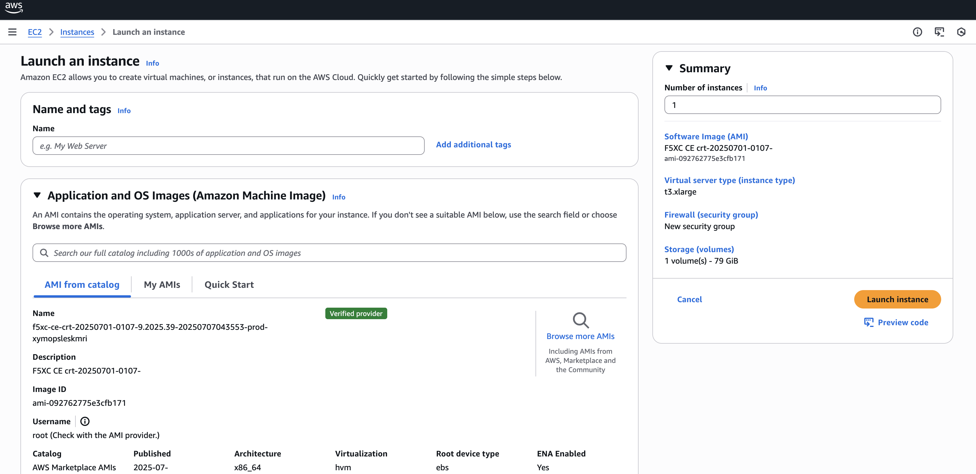
Figure: Configure Node VM Settings
-
Click Add additional tags and add the two following tags:
-
ves-io-site-name (key): This value equals the Secure Mesh Site object name from the Create Site Object section. This tag is mandatory.
-
kubernetes.io/cluster/ (key): The value after /cluster/ is the Secure Mesh Site object name from the Create Site Object section. This tag is optional and is only useful if your CE is used as a container ingress service with AWS EKS.
-
-
Keep Application and OS Images (Amazon Machine Image) set to the default AMI listing.
Step 2.1: Configure compute resources.
From the Instance Type menu, select the compute resources required for your node VM. F5 recommends using the m5.2xlarge option. This is the minimum instance type required to run F5 CE Site software. Refer to the Customer Edge Site Sizing Reference guide for more information.
Step 2.2: Select SSH key pair.
From the Key pair name - required menu, select the SSH key pair previously created in section Create SSH Key Pair.
Step 2.3: Configure network interface subnet settings.
The subnet chosen in this step is the subnet for the first interface (SLO). Labeling the subnets helps so that you can easily place the interface in the SLO subnet. Optionally, if you want additional interfaces, you can configure and add them in this step. Those additional interfaces are the SLI (for example, you can label them as “SLI1”, “SLI2”, and so on). Note that each network interface must be assigned to a different subnet.
-
Select Edit.
-
Ensure you select the correct VPC and subnet(s).
-
Ensure that Auto-assign public IP is disabled as the Elastic IP address (or any other method for public Internet access) is used instead.
-
Optionally, assign additional (secondary) IP addresses to the SLO or SLI to be used as custom VIPs under Advanced network configuration.
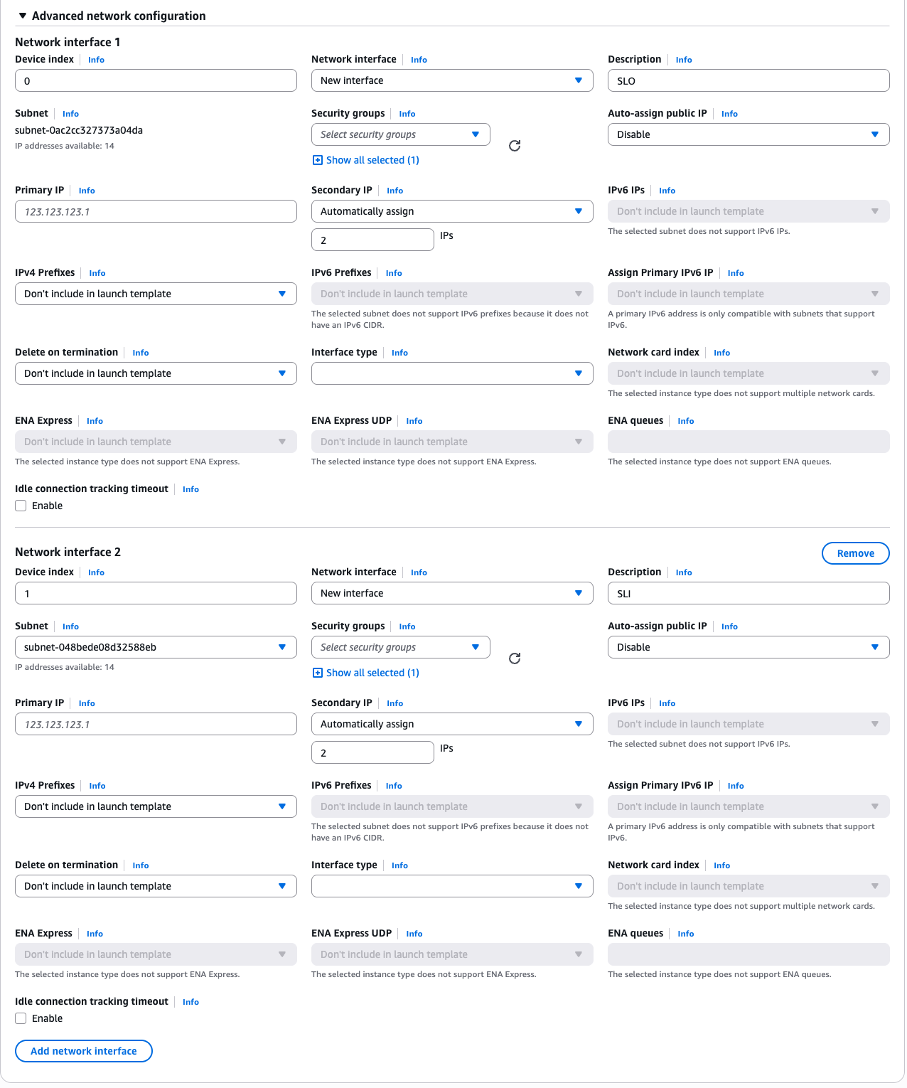
Figure: Add Network Interface(s)
Step 2.4: Configure security group settings.
Under Firewall (security groups), select the security group created previously in section Create Security Group.
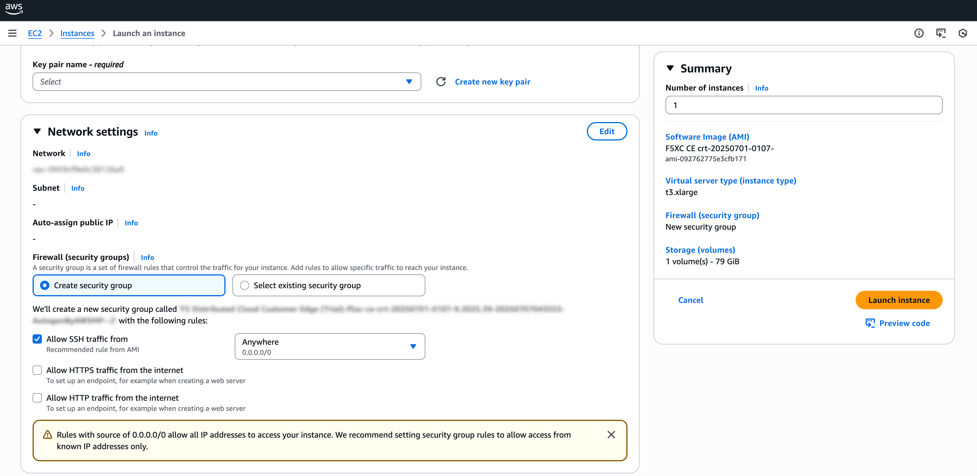
Figure: Add Security Group
Step 2.5: Configure node VM storage.
Under Configure storage, enter an amount. The minimum required is 80 GB.
Step 2.6: Configure node VM user data.
-
Expand the Advanced details field.
-
Under User data - optional, paste your cloud-init script information (which includes the node token) from section Generate Node Token.
Step 3: Complete configuration and deploy node VM.
After you complete the required configuration settings, click Launch instance.
Create Elastic IP Address - Optional
Each CE node requires outbound Internet access to register with Distributed Cloud Console. One simple way to achieve this is to create and attach one Elastic IP Address (EIP) per node to the SLO interface. However, this is not the only method. You can alternatively use a NAT Gateway or leverage your existing AWS network architecture to provide outbound connectivity. For the sake of simplicity, this guide demonstrates the EIP method.
-
In AWS Management Console, navigate to Network & Security > Elastic IPs.
-
Click Allocate Elastic IP address.
-
Confirm Network border group is set as desired.
-
Select Add new tag.
-
Ensure Name is selected for Key.
-
Enter a value for the EIP address in the Value - optional field. This example uses f5-ce-eip.
-
Select Allocate.
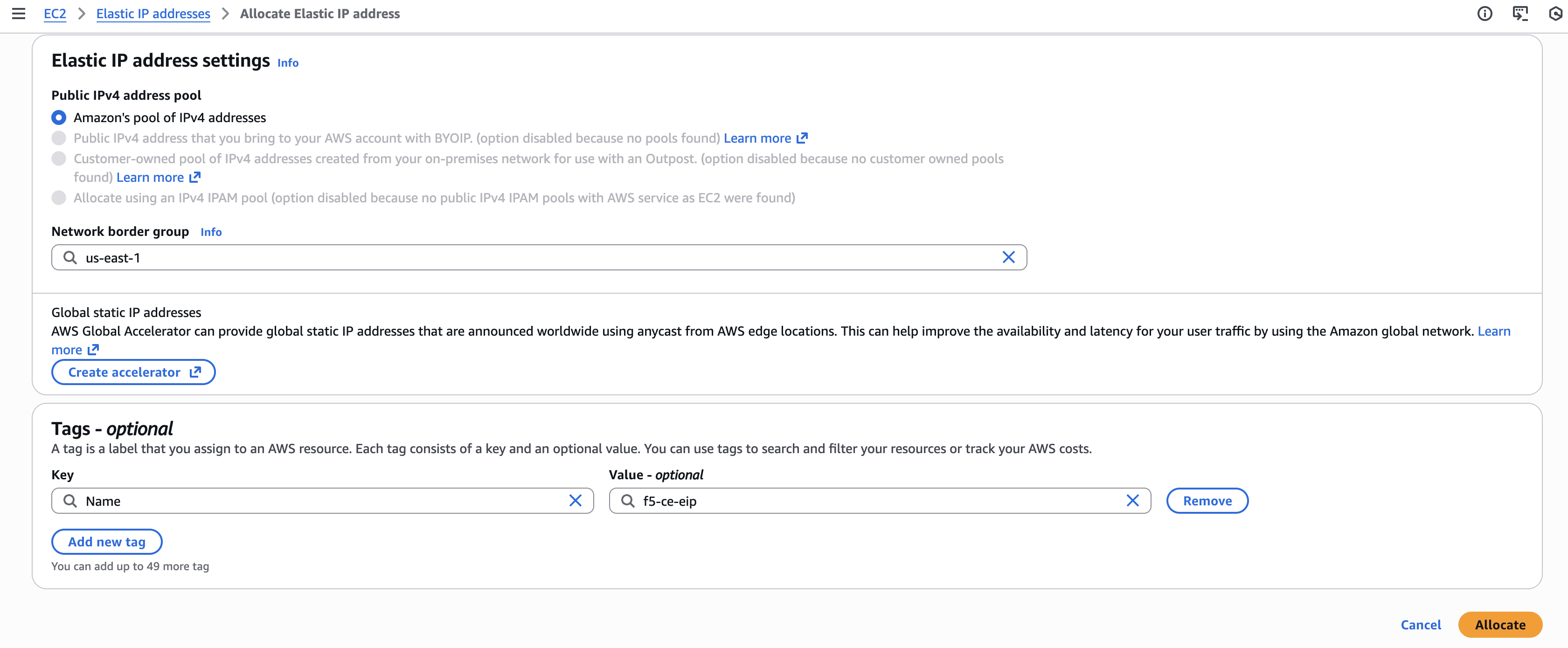
Figure: Configure EIP Address
Provide Outbound Internet Access for Each Node
After the EC2 instance VM is created, you need to provide outbound Internet access for each node of your CE Site. There are many methods to provide access, but the simplest method is to allocate the previously created Elastic IP address.
-
Take note of the SLO interface ID by navigating to the Networking tab under your F5 CE node instance and getting the ENI ID of the SLO interface. Keep it handy as you need it when assigning the Elastic IP address to the SLO interface.
-
In the EC2 Console, select Networking & Security > Elastic IPs.
-
Search for your EIP address and then select it.
-
From the Actions drop-down menu, select Associate Elastic IP address.
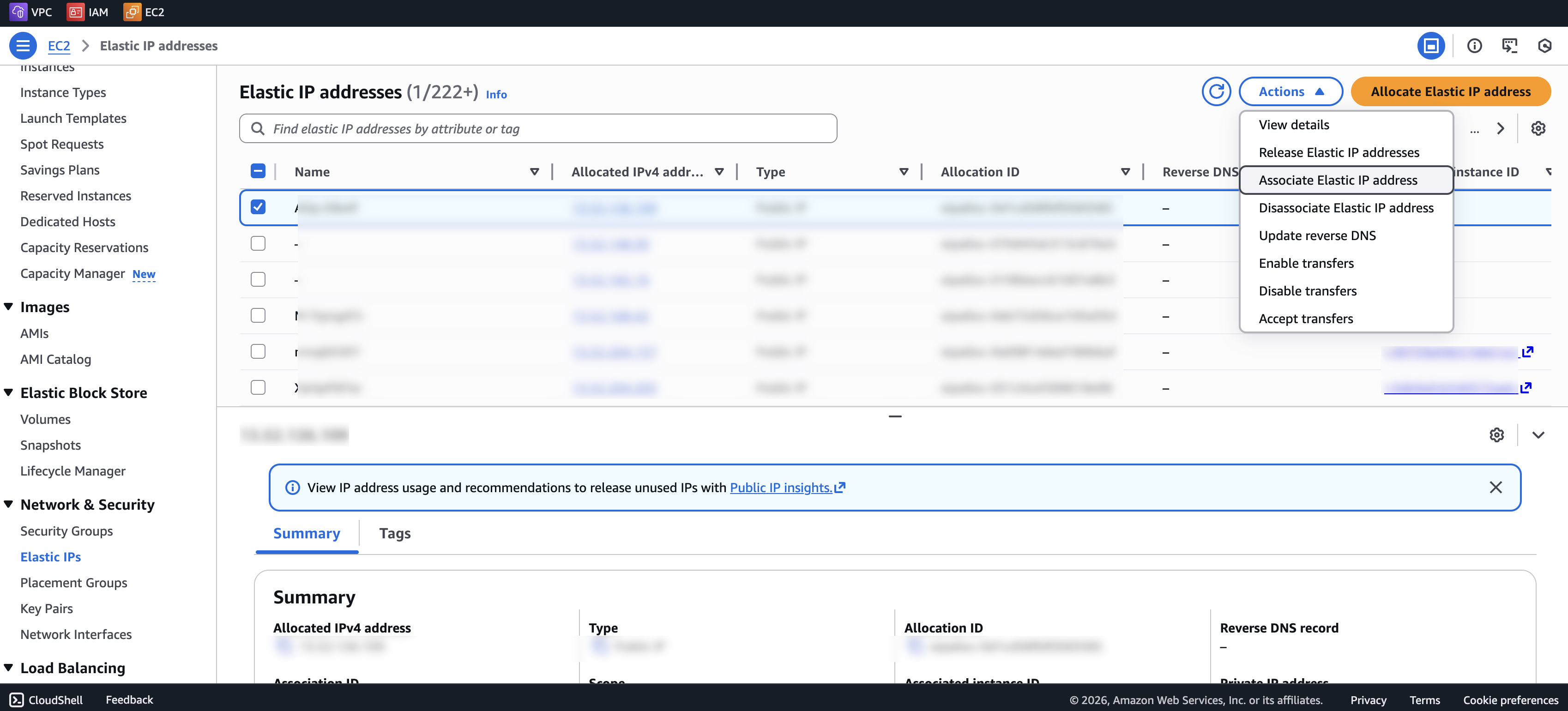
Figure: Associate EIP Address
-
Select the Resource type as Network interface.
-
From the Network interface menu, select the SLO interface.
-
Click Associate.
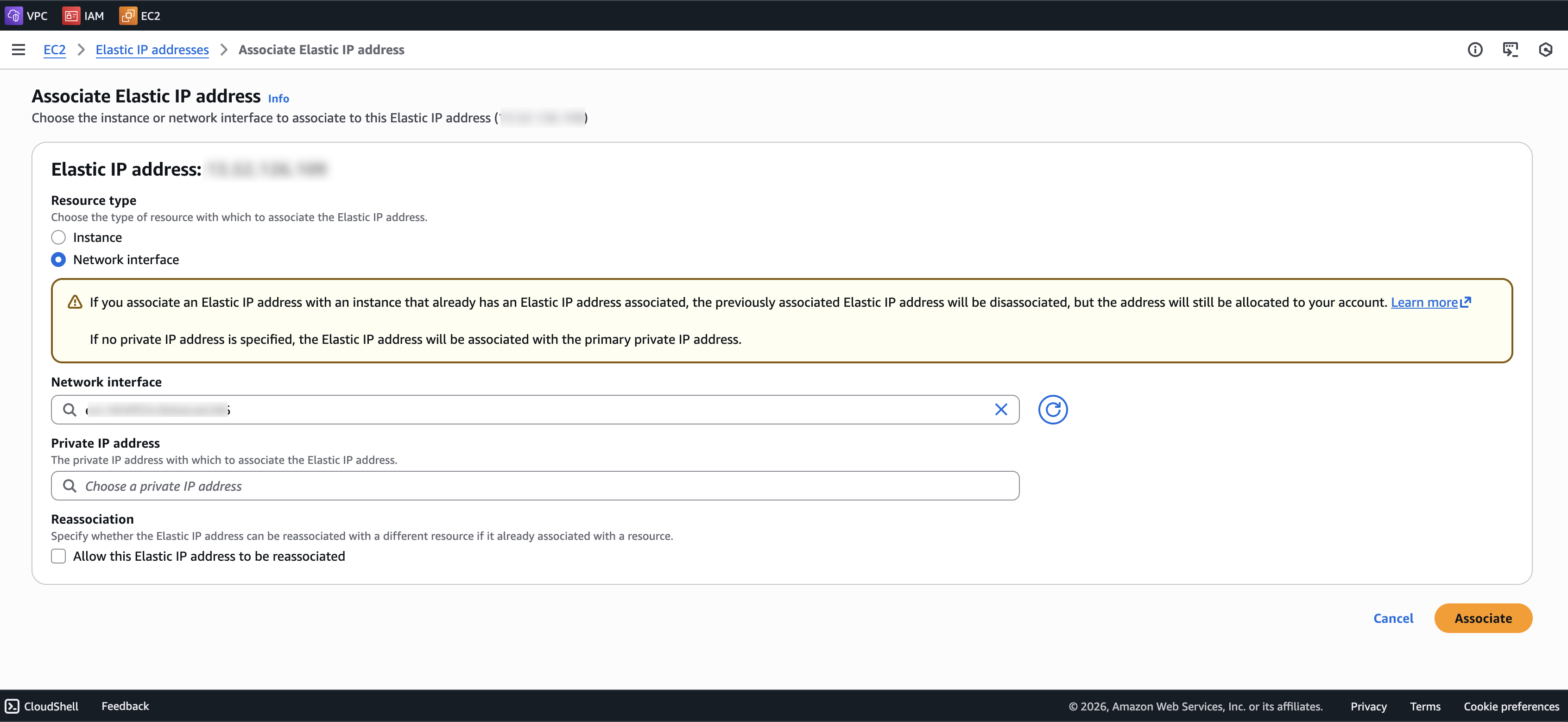
Figure: Associate EIP Address
Verify CE Site Registration
After you deploy your nodes, they automatically register as a CE Site in Distributed Cloud Console. The registration process is not instantaneous. In Console, the status changes from Waiting for Registration to Provisioning to Online. Wait a few minutes for the registration process to begin after completing the preceding sections.
-
In Distributed Cloud Console, navigate to Multi-Cloud Network Connect > Overview > Infrastructure > Sites.
-
Select your CE Site. The Dashboard tab should clearly show that the CE Site has registered successfully with the System Health of 100% as well as Data Plane/Control Plane both Up.
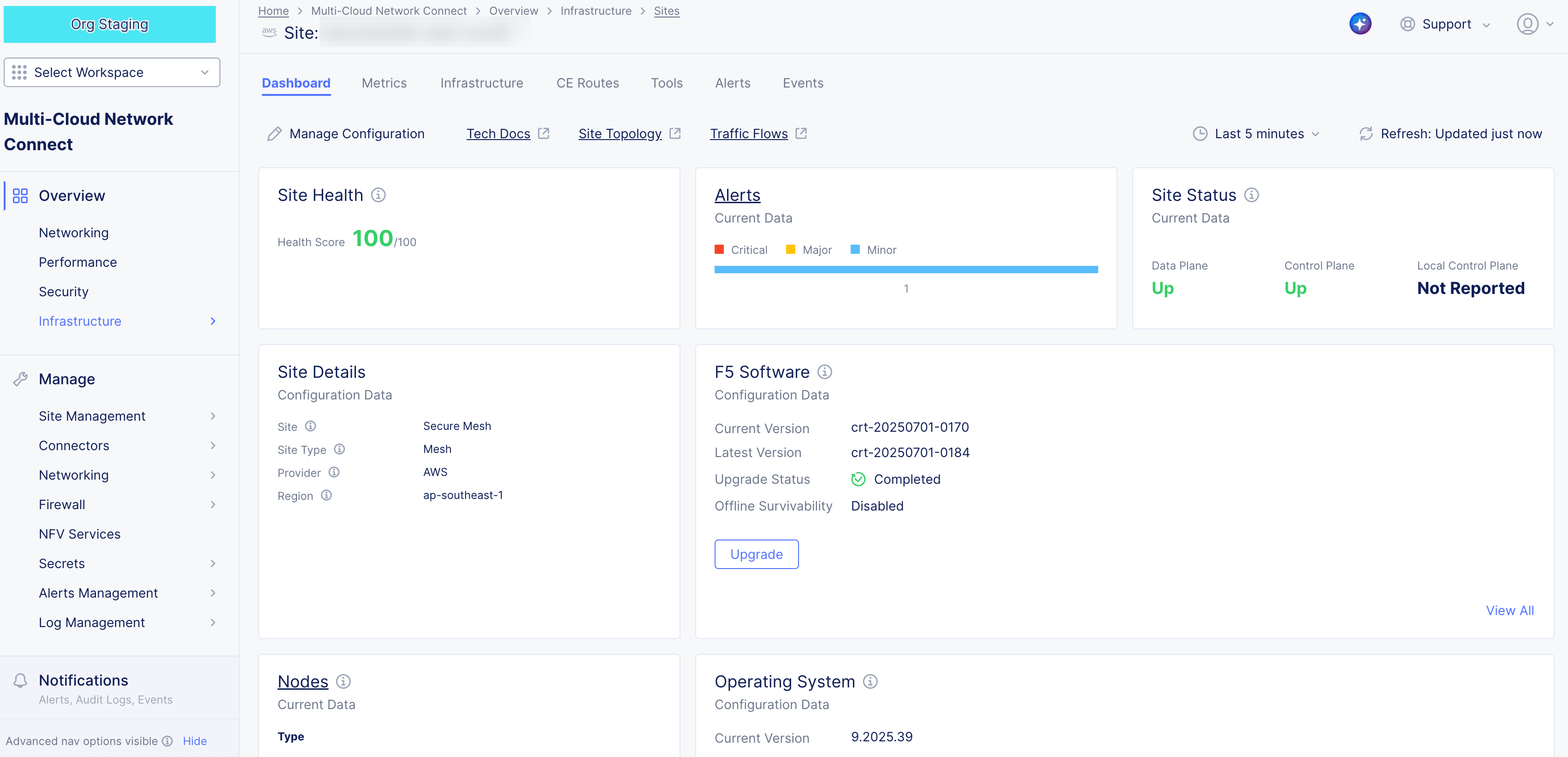
Figure: Confirm Site Health
Note: For more information on the CE Site registration process, see the Customer Edge Registration and Upgrade Reference guide.
Post-Deployment Configuration - Optional
After your CE Site registers successfully, you might want to add additional network interfaces to meet your requirements. Ensure that you connect another network interface to the node VM.
Important: Adding or removing network interfaces causes the data plane services on the CE node to restart. Therefore, F5 strongly recommends that you perform this operation during maintenance windows. As data plane services restart, traffic drops are expected, as well as tunnels to F5 Distributed Cloud REs going down.
All CE nodes in a given multi-node Site should have the same number of network interfaces attached. CE nodes with non-homogenous interfaces within a CE Site might cause issues.
Each node in a multi-node CE Site should have interfaces with the same VRFs assigned. For example: If a CE Site has three nodes, with each node having two interfaces - the first interface on each node is auto-configured to be in the SLO VRF (to connect to F5 Distributed Cloud). If the second interface on node-1 is in the SLI VRF, then the second interface on node-2 and node-3 must also be in the SLI VRF.
When new interfaces are added, they are auto-discovered. You can configure the interface (for example: place the interface in the appropriate VRF) from the CE Site configuration.
The first interface of the CE nodes should not be removed or modified.
After you configure the SLO interface with a static IP address, DHCP will still be displayed in the Console. However, your static IP configuration is well taken into account. Also, remember that you cannot modify SLO parameters once the node is registered and deployed.
Modify Interface Attributes
Important: The IP address for the SLO interface cannot be modified. In addition, you cannot modify any MAC addresses for any interfaces.
-
Power down the VM prior to adding any new interfaces or modifying any existing interfaces.
-
To modify any interface attributes, click Manage Configuration.
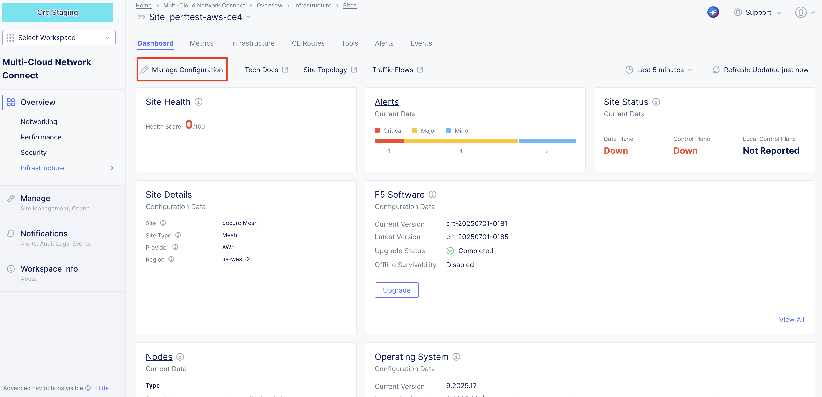
Figure: Edit Interface
- Click Edit Configuration.
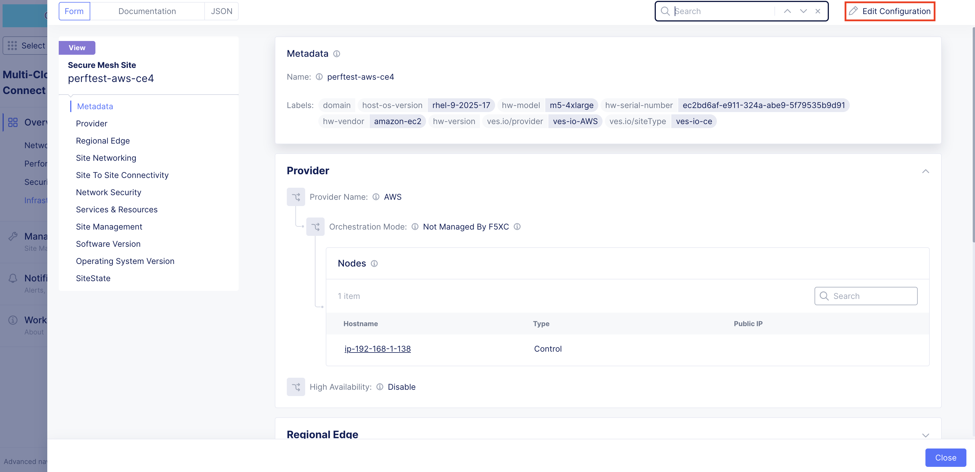
Figure: Edit Interface
- Under the Nodes subsection, click the pencil icon under Actions to edit.
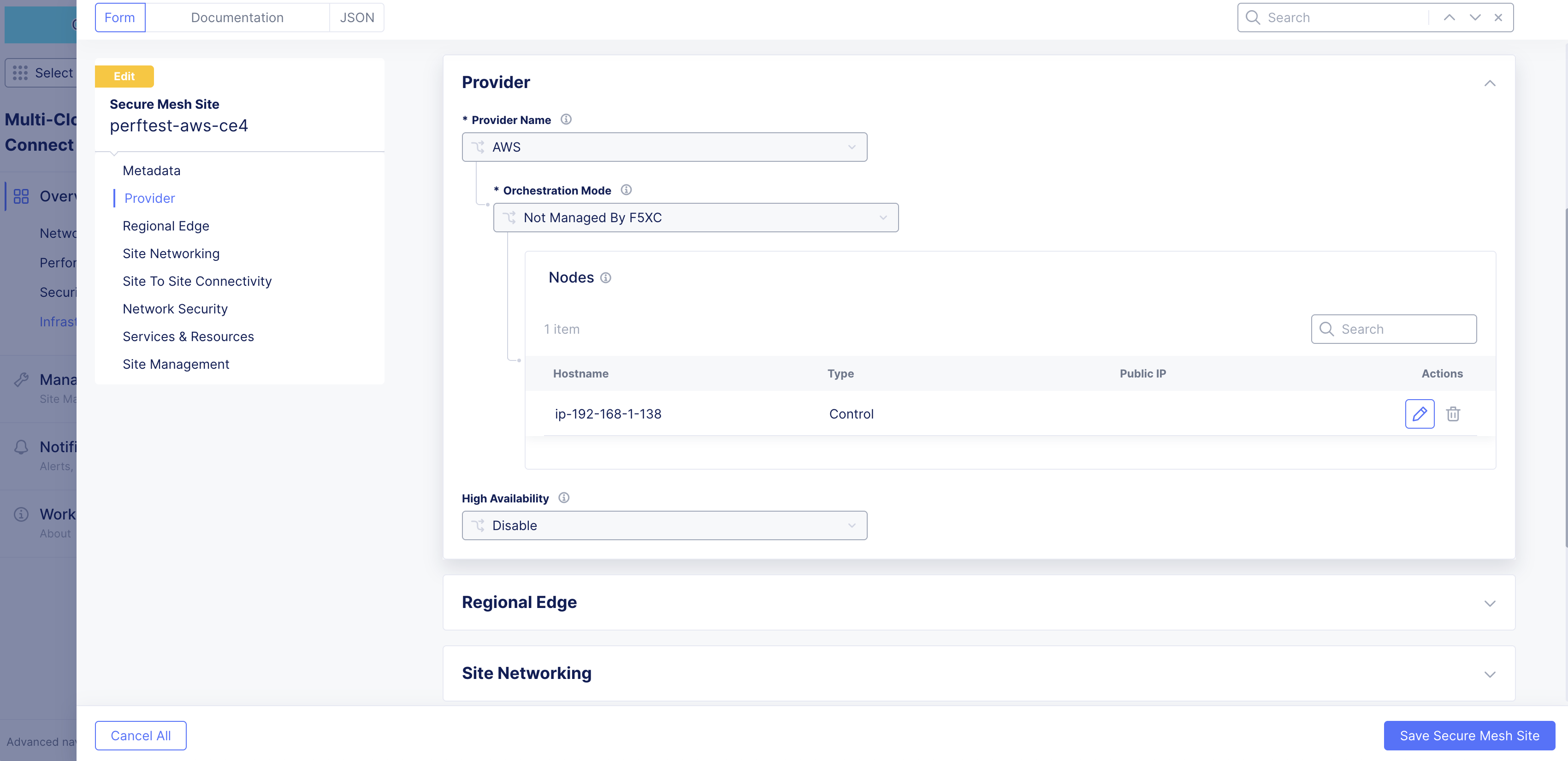
Figure: Edit Interface
- Choose one of the interfaces to edit. This example uses ens6.
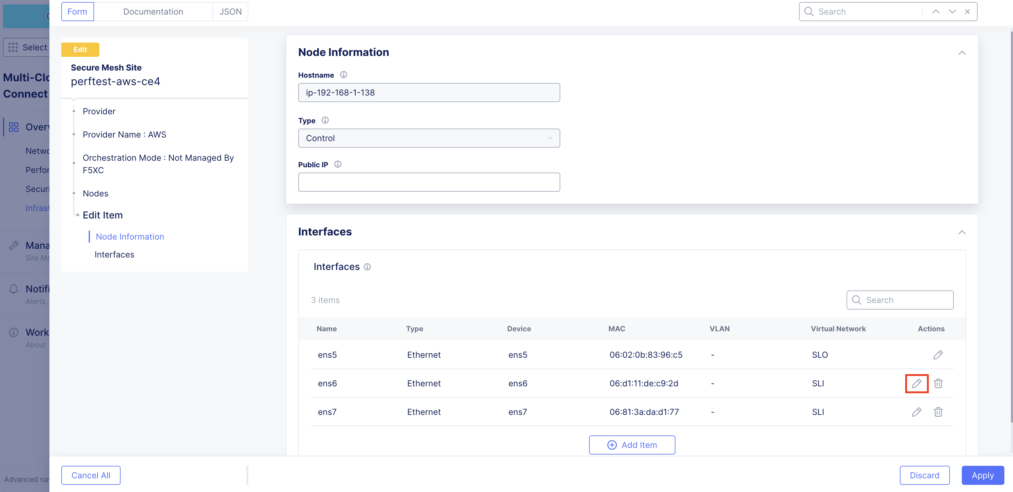
Figure: Edit Interface
- Change the settings as required. In this example, the interface is being placed in the prod-segment. Therefore, the setting from the original Site Local Inside (Local VRF) to Segment (Global VRF) was changed. Then, the required segment is selected.
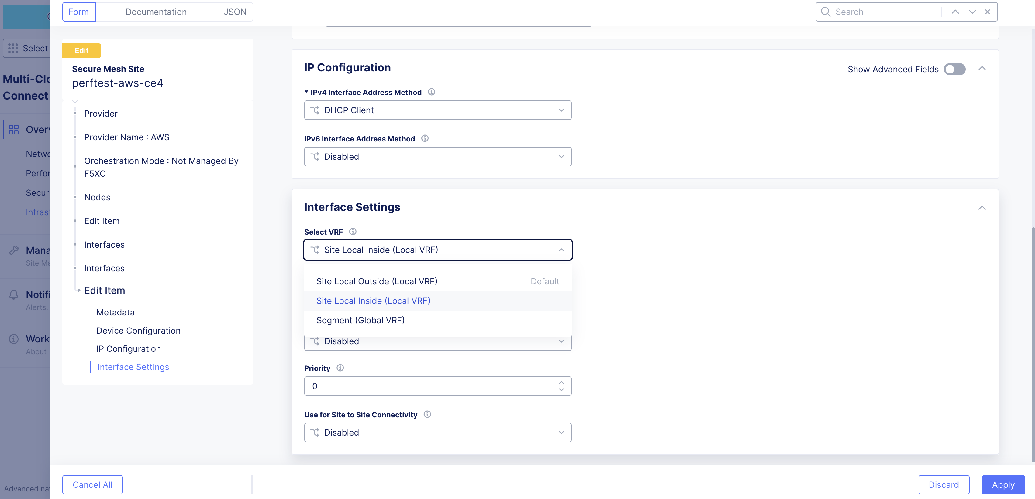
Figure: Edit Interface
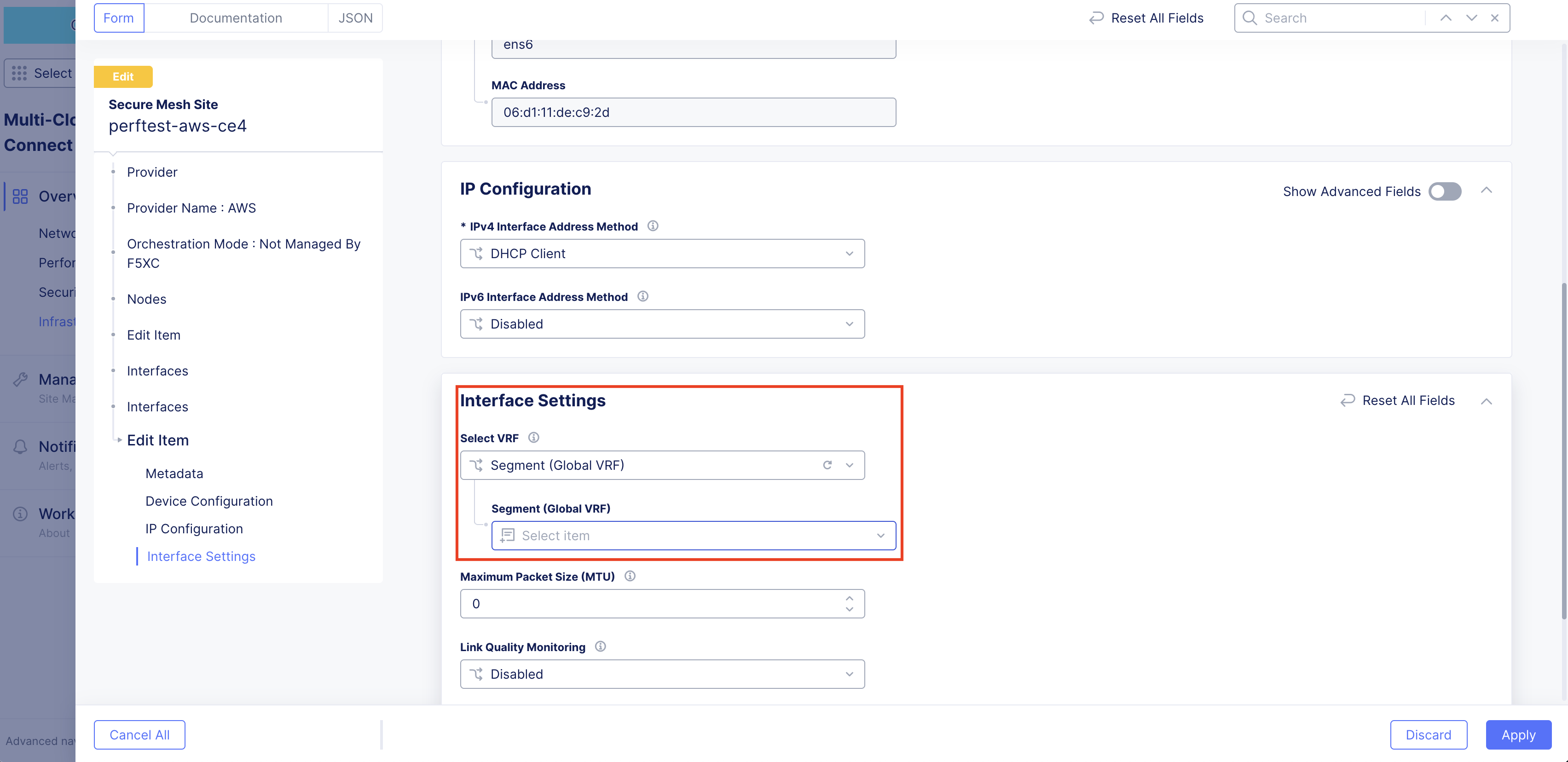
Figure: Edit Interface
-
Click Apply to apply the interface attribute changes.
-
Click Apply again to confirm interface attribute changes.
-
Click Save Secure Mesh Site.
-
In the AWS Management Console, power back up the node VM.
Stop Source/Destination Checks
In AWS, the source/destination check is a feature that ensures that an EC2 instance is only responsible for traffic that it sends or receives. By default, this check is enabled for all EC2 instances, meaning that each instance is expected to handle only the network traffic that originates from or is destined to its own IP address.
In the case of an F5 CE Site, the instance is a Network Virtual Appliance (NVA) that outgoing and incoming traffic needs to transit through. Therefore, you need to disable the source/destination check on the F5 CE EC2 instance.
-
In AWS Management Console, navigate to the EC2 service.
-
For your EC2 instance, select Actions > Networking > Change source/destination check.
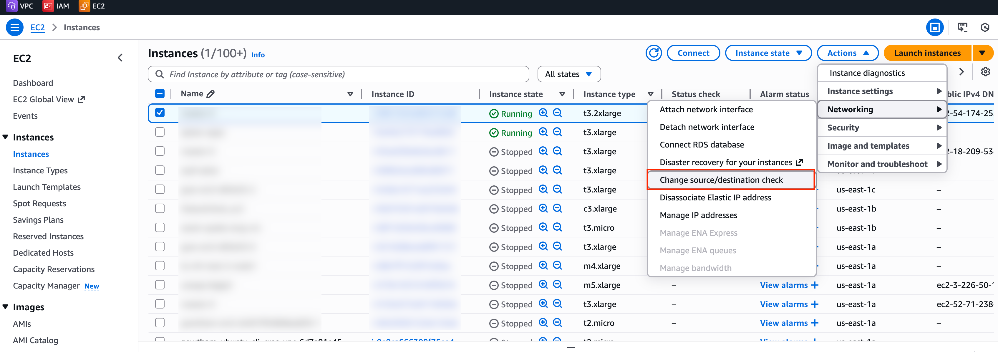
Figure: EC2 Instance Networking
- Check the box for Stop.
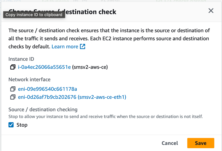
Figure: Stop Checkbox
- Click Save.
Add New Interface Post Deployment
For AWS sites, to add another network interface to the CE, you need to create a new network interface as part of the same VPC in a different subnet with auto-assigned addresses preferably and attach a security group to the interface.
In the example below, the default VPC security group allows traffic in both directions, as this is an internal-only interface. You can also provision additional security groups with more restrictive policies on the non-SLO interfaces if required and provided you have a full understanding on the nature of traffic that traverses the interfaces. Tagging the interface with the instance name is a good practice to easily understand the reason behind this interface.
Step 1: Create new network interface for EC2 instance.
-
In the EC2 service, navigate to Network & Security > Network Interfaces.
-
Select Create network interface.
-
Under the Description - optional field, enter a name for the new interface.
-
From the Subnet drop-down menu, select the subnet for this new interface.
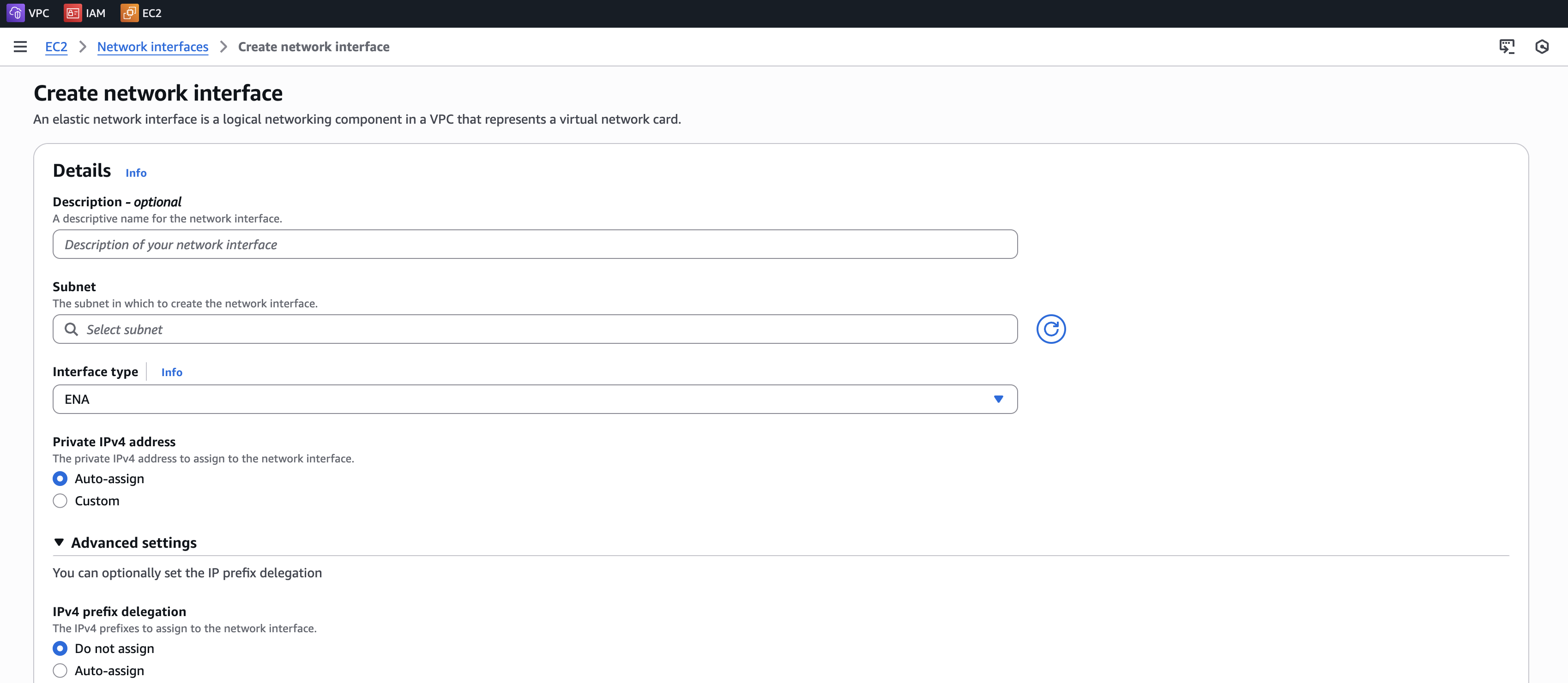
Figure: Add New Interface
-
Add a name tag for this new interface.
-
Click Create network interface.
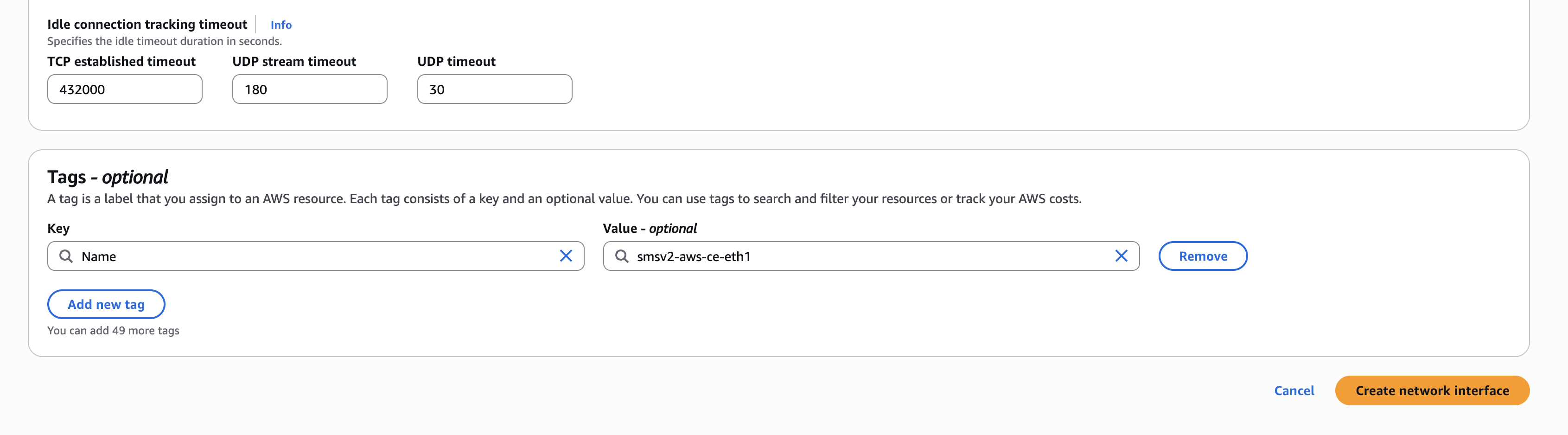
Figure: Add New Interface
Step 2: Attach new network interface to EC2 instance.
-
Power down the VM prior to adding any new interfaces or modifying any existing interfaces.
-
After the interface is created, attach it to the particular instance. Select the particular interface you created and click Actions > Attach.
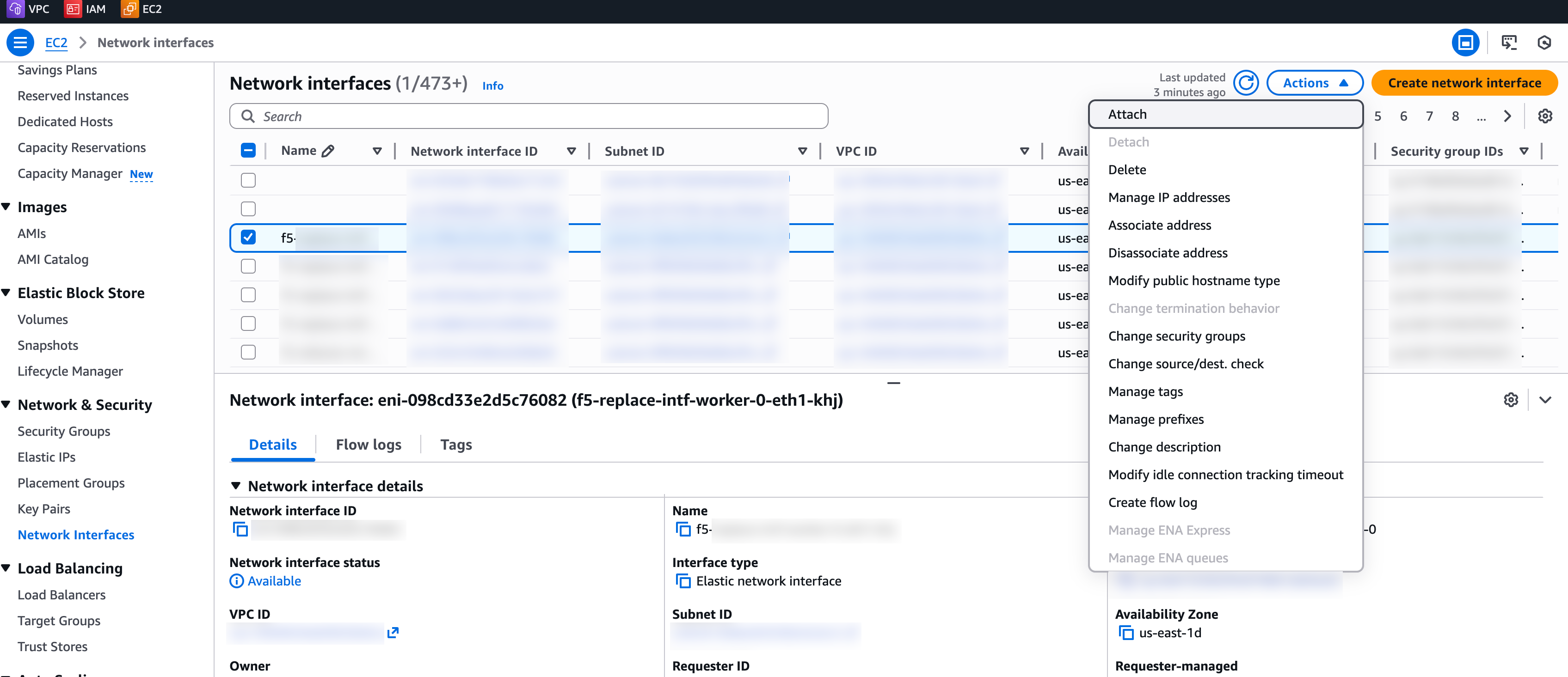
Figure: Attach to Instance
-
Specify the correct details of the VPC and instance and then click Attach.
-
In Console, navigate to your Site and edit the node configuration.
Figure: Edit Interface
-
For the desired interface, click the pencil button.
-
Ensure you set the IPv4 Interface Address Method as DHCP Client.
-
Click Apply, and then click Save Secure Mesh Site.
Step 3: Verify changes in AWS Management Console.
Verify in AWS Management Console that the EC2 instance, under the Networking tab, now has two interfaces.
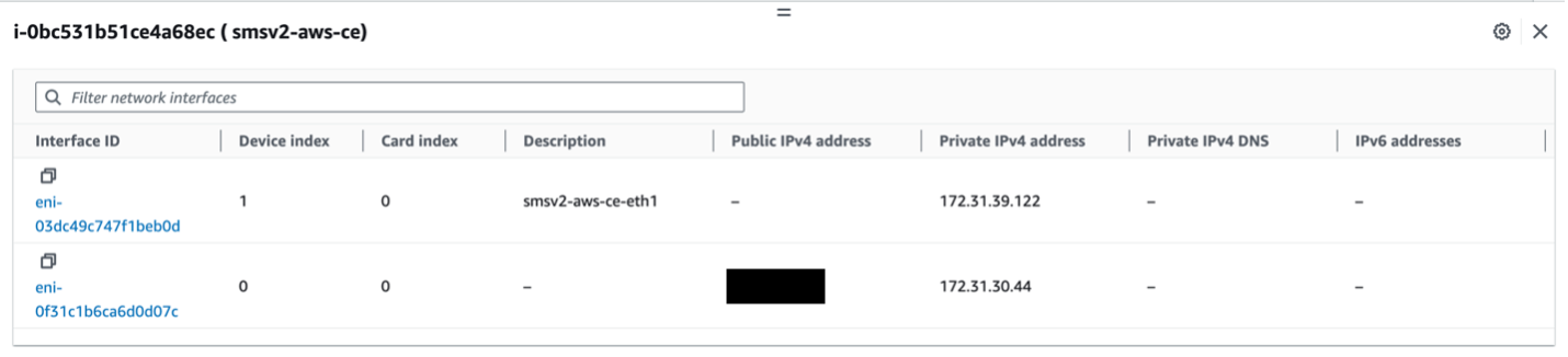
Figure: Verify Changes in AWS
Step 4: Verify changes in Distributed Cloud Console.
-
Power back up the VM.
-
You can also verify the same information from Distributed Cloud Console by navigating to the Site Dashboard under Multi-Cloud Network Connect > Overview > Sites and choosing the Site name. Navigate to the Infrastructure tab to see the Interfaces table.
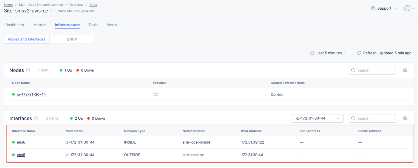
Figure: Verify Changes in Console
Troubleshooting for AMI Listings
While the AMIs are published across all global regions, there might be cases where the AMI does not exist (for example, a new region just went online). If you previously found the AMI listing above, you can skip this troubleshooting section. This section explains how you can still deploy CE Site nodes in regions where the official F5 AMI listing does not exist.
You can use the functionality within AWS by navigating to the official AWS documentation and following the required steps.
Important: Note that after you copy the AMI to your region, it becomes a private AMI. In other words, it is only accessible to your account, whereas the original AMI is a public AMI for all other customers to consume.
-
Copy the image name from Distributed Cloud Console.
-
Switch to us-east-1 in the AWS Management Console and locate the AMI by its name as described in section Create AWS EC2 Instance above.
-
Select the AMI and then click Actions > Copy AMI.
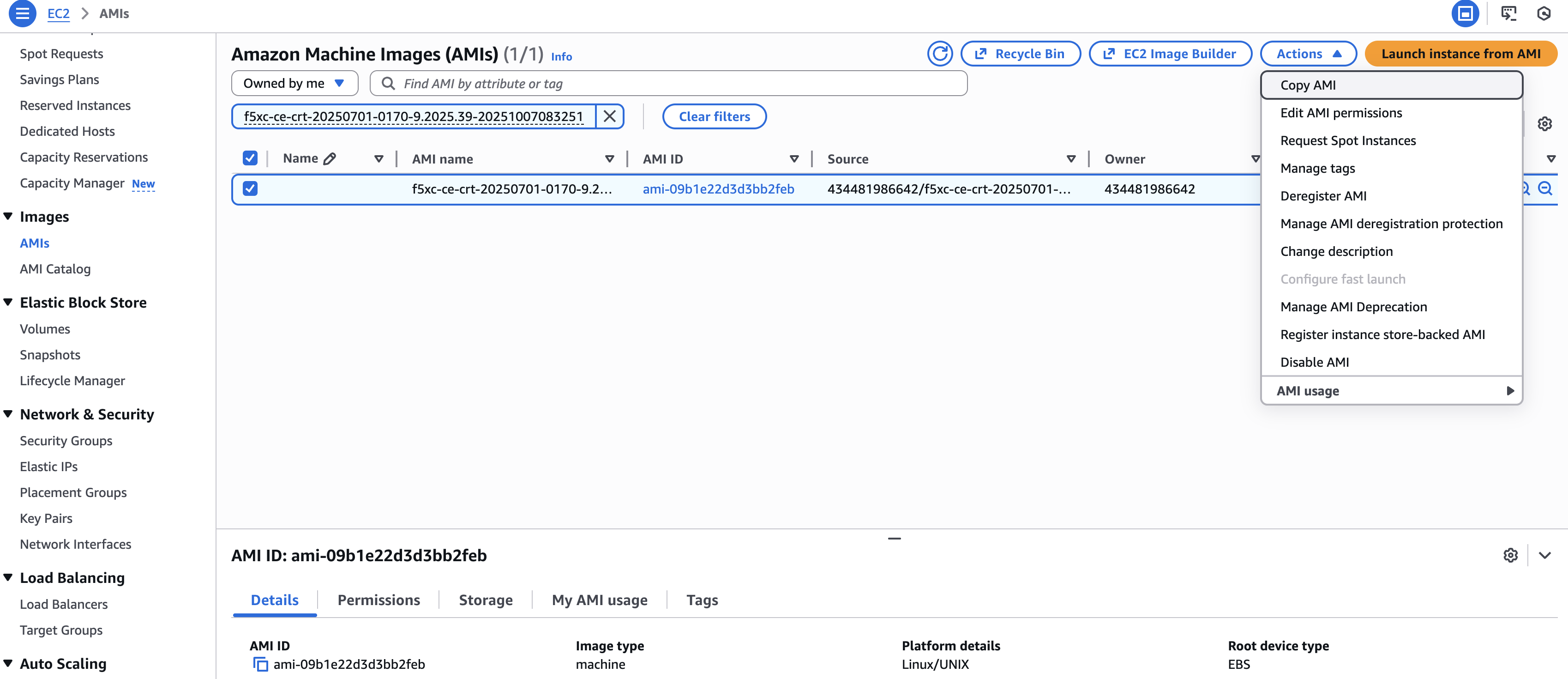
Figure: Copy AMI to Target Region
-
Enter a copy name and a copy description. F5 recommends that you keep the name and description matching to the original name or, at a minimum, provide meaningful names that help you distinguish the new private AMI.
-
From the Destination Region drop-down menu, select the new region to copy the AMI to.
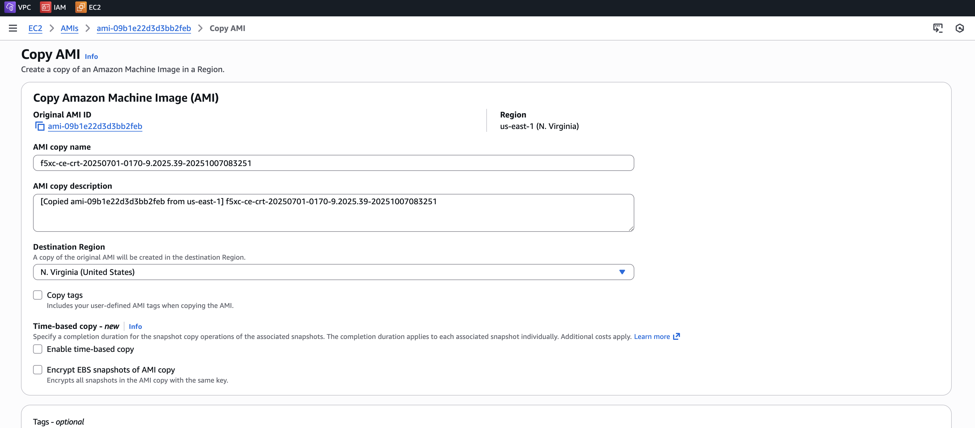
Figure: Copy AMI to Target Region
- Click Copy AMI.
Day 2 Operations
- To monitor your Site, see the Monitor Site guide.
- To manage your Site software and OS updates, see the Manage Site guide.
- For troubleshooting issues, see the Troubleshooting Guide for Secure Mesh Site v2 Deployment guide. It provides step-by-step instructions to debug and resolve the issues that may arise due to registration and provisioning errors.
- For the latest on Distributed Cloud Services releases, see Changelogs.
- To view the various types of events generated, see the Events Reference guide.
Related Guides
To create a load balancer on the CE Site, see the HTTP Load Balancer or the TCP Load Balancer guides.
Concepts
On this page:
- Objective
- Planning
- General Prerequisites
- Configuration Overview
- High Availability Option for Redundancy
- Configuration in Distributed Cloud Console
- Create Site Object
- Generate Node Token
- Configuration in AWS Management Console
- Prepare VPC Resources
- Create Security Group
- Create SSH Key Pair - Optional
- Create AWS EC2 Instance
- Create Elastic IP Address - Optional
- Provide Outbound Internet Access for Each Node
- Verify CE Site Registration
- Post-Deployment Configuration - Optional
- Modify Interface Attributes
- Stop Source/Destination Checks
- Add New Interface Post Deployment
- Troubleshooting for AMI Listings
- Day 2 Operations
- Related Guides
- Concepts